
Roofing systems for steep pitch metal roofing

a technology of metal roofing and roof, applied in roof coverings, roofs, roofs, etc., can solve problems such as future leakage and buckling

Inactive Publication Date: 2019-06-18
SOUTHEASTERN METALS MFG
View PDF11 Cites 2 Cited by
  • Summary
  • Abstract
  • Description
  • Claims
  • Application Information

AI Technical Summary

Benefits of technology

This solution provides a faster installation, reduces production time, minimizes dimpling effects, and prevents leaks by eliminating screw penetration, while maintaining a clean appearance and allowing for natural panel expansion and contraction.

Problems solved by technology

One problem with this method of attaching metal roofing plates is that each screw through the metal creates a source for future leaks and buckling.

Method used


Image

  • Roofing systems for steep pitch metal roofing
  • Roofing systems for steep pitch metal roofing
  • Roofing systems for steep pitch metal roofing

Examples


Embodiment Construction

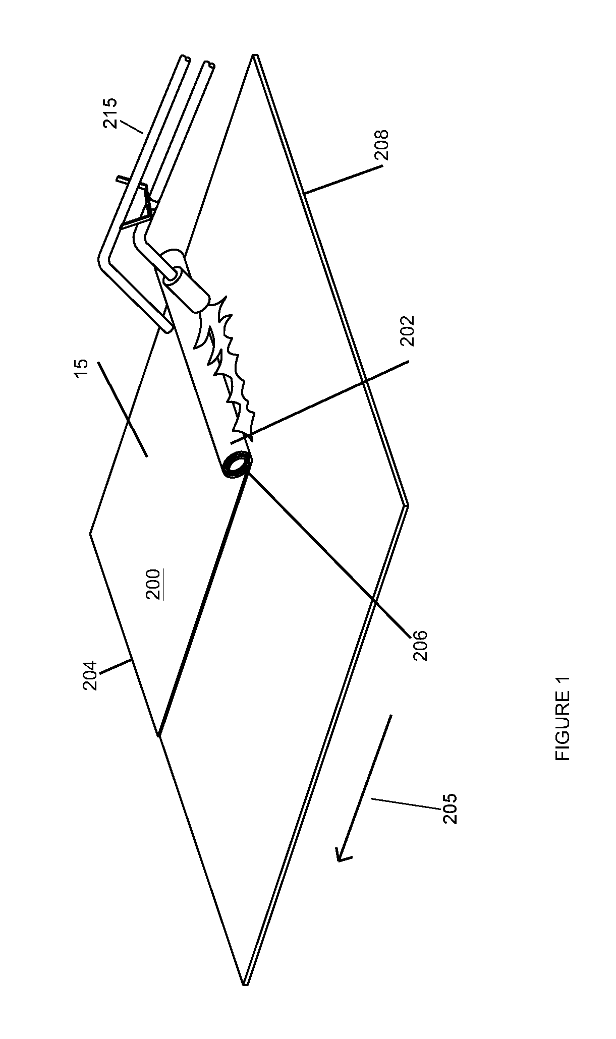
[0013]The present invention provides a roofing system, comprising: at least one underlayment layer, which may be a roll (15) having a top (200), a bottom (202), first end (204) and a second end and being impermeable to moisture. The underlayment layer may be breathable, but does not allow moisture to permeate. The second end (206) of the roll is at the end of the roll. The first end (204) of the underlayment roll (15) is fastened over a center of a top rib in a roof deck and the underlayment roll is dispensed in a first row and cut at the end of the roof deck (208) creating a cut end (210) and fastened at the cut end. The cut end (210) may be additionally fastened by nail fasteners, for example roofing gun nails (in addition to the adhesive). The head of each of the nail fasteners is above the at underlayment layer and the shaft of the nail fastener is driven through the underlayment layer and into the roof deck. The nail fasteners may be ring shank roofing nails. The nail fasteners...


PUM


Abstract

A roofing system having at least one underlayment layer; at least two nail fasteners attached to the at least one underlayment layer and into the roof deck, wherein the head of each of the nail fasteners is above the at underlayment layer and the shaft is driven through the underlayment layer and into the roof deck; at least one bead of adhesive applied above the underlayment layer; and at least one metal roofing panels placed on the at least one bead of adhesive applied above the underlayment layer, wherein the at least one metal roofing panels are above the at least two nail fasteners and the at least two nail fasteners do not penetrate the at least one metal roofing panels.

Description

[0001]The present invention relates to metal roofing systems having a steep pitch slope.[0002]Low Slope Roofing is less than 2:12 to flat built up roofing. The present invention is directed to the particular problems posed by Steep Pitch Metal Roofs which are greater than 2:12. The pitch of a roof is its vertical rise divided by its horizontal span (or “run”), what is called “slope” in geometry and stair construction. In the USA, the run is denominated by the number 12, giving a ratio of how many inches of rise or fall there are to each 12 inches (one foot) of run. For example, 3:12, 4:12, 5:12, and so on.[0003]The present invention is utilized in lieu of the screw attached 3″-6″ metal plates which are the current industry attachment method. One problem with this method of attaching metal roofing plates is that each screw through the metal creates a source for future leaks and buckling.[0004]The systems and methods of the present invention provide a metal roofing panel fastener syst...

Claims


Application Information

Patent Timeline
Patent Type & Authority Patents(United States)
IPC IPC(8): E04D5/14E04D1/18E04D1/34E04D3/16E04D12/00
CPCE04D5/144E04D1/18E04D1/34E04D3/16E04D5/141E04D5/149E04D12/002E04D2001/3435
Inventor HORTON, JAMES W.
Owner SOUTHEASTERN METALS MFG
Learn More