Offshore platform lifting device

a platform and lifting technology, applied in the direction of hoisting equipment, transportation and packaging, passenger handling apparatus, etc., can solve the problems of reducing the total production cost effectively and the cost of offshore lifting, and achieve the effect of economic and stable manner

Inactive Publication Date: 2019-06-04
SEA ENERGY TECH
View PDF8 Cites 0 Cited by
  • Summary
  • Abstract
  • Description
  • Claims
  • Application Information

AI Technical Summary

Benefits of technology

[0005]The primary object of the present invention is to provide an offshore platform lifting device, which uses support legs filled with seawater to sink to the seabed and a lower pontoon filled with seawater to move down toward the sea surface, thereby positioning the offshore platform lifting device in an economical and stable manner.
[0006]Another object of the present invention is to provide an offshore platform lifting device, which provides third winches to wind / unwind third cables for two davit arms to move laterally along a curved rail, in cooperation with second winches to wind / unwind second cables for lifting and lowering a heavy object hanged by hooks of the davit arms. The offshore platform lifting device not only allows the davit arms to load and lift the heavy object but also reduces the total production cost effectively and the cost of offshore lifting through the simple design of the overall structure.
[0009]Preferably, each upright column is provided with a wave-dissipating channel. The wave-dissipating channel has through holes on a plurality of sides of the upright column. The through holes communicate with each other through a pipe in the upright column. When a wave meets the upright column, seawater flows in through one of through holes and flows out through the other through holes via the pipe to eliminate the force of the wave against the upright column.

Problems solved by technology

The offshore platform lifting device not only allows the davit arms to load and lift the heavy object but also reduces the total production cost effectively and the cost of offshore lifting through the simple design of the overall structure.

Method used


Image

  • Offshore platform lifting device
  • Offshore platform lifting device
  • Offshore platform lifting device

Examples


Embodiment Construction

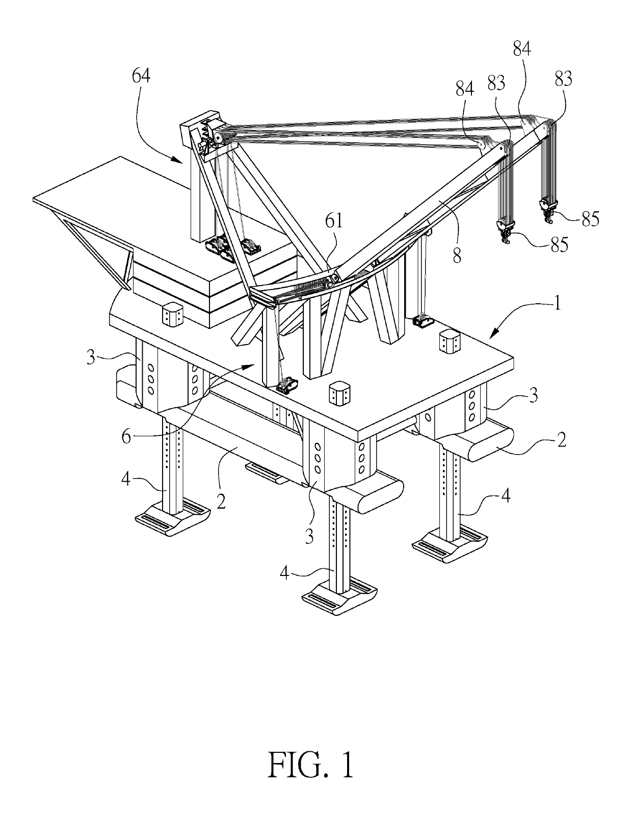
[0029]The present invention provides an offshore platform lifting device for lifting operations at sea after sailed to a certain position of a sea surface A. As shown in FIG. 1, the offshore platform lifting device mainly comprises an upper deck 1, a plurality of upright columns 3, a rail seat 6, a base 7, two davit arms 8, two first winches 91, and two second winches 92.

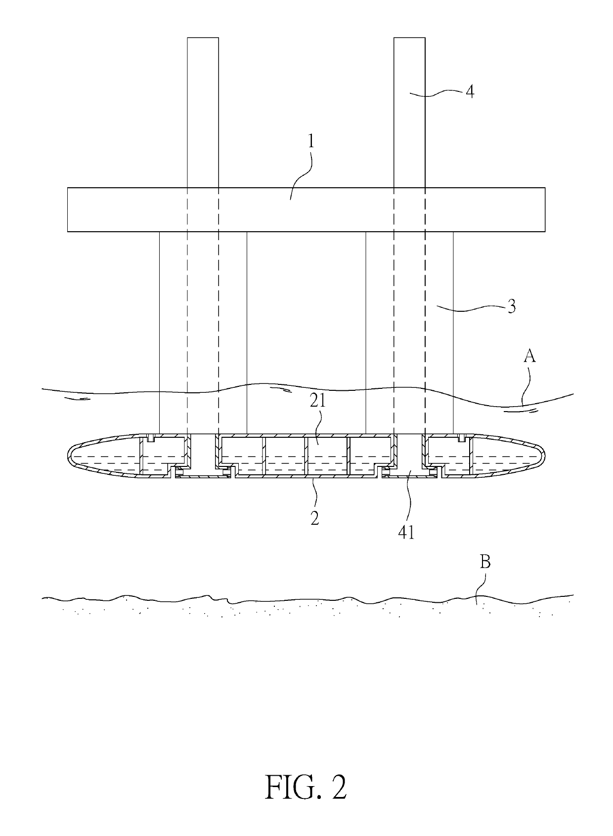
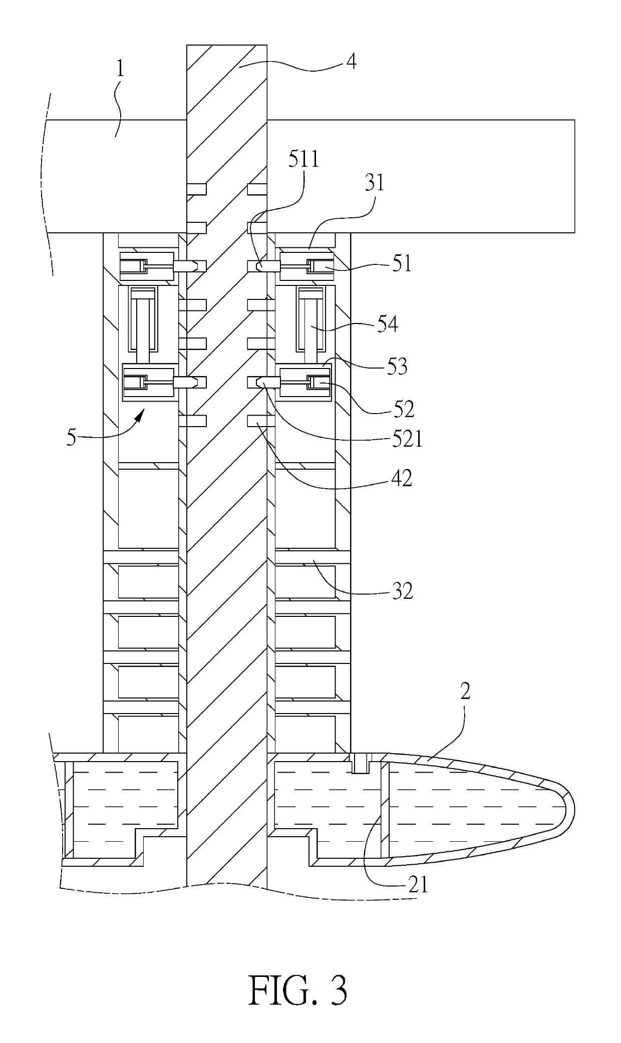
[0030]As shown in FIG. 2, the upper deck 1 is connected to a lower pontoon 2 by the respective upright columns 3. Each upright column 3 is provided with a support leg 4 that is longitudinally inserted through the upright column 3. The lower pontoon 2 has a plurality of chambers 21 therein. The chambers 21 are configured to receive water therein so that the lower pontoon 2 can sink downwardly when the water is introduced into the chambers 21 or float upwardly when the water is drained out. The operator can adjust the overall center of gravity of the offshore platform lifting device by controlling water filling into o...


PUM


Abstract

An offshore platform lifting device for lifting operations at sea after sailed to a certain position of a sea surface includes an upper deck, a plurality of upright columns, a rail seat, a base disposed on the rail seat, two davit arms, two first winches, and two second winches. The upper deck has a lower pontoon. The upright columns are connected between to the upper deck and the lower pontoon. Each upright column is provided with a support leg that is longitudinally inserted through the upright column, thereby positioning the offshore platform lifting device on the seabed through the upright columns. The two davit arms are disposed the base and drives the base to move laterally through a pushing device. The two second winches each have a second cable passing through the two davit arms. A hook is disposed at a distal end of the second cable.

Description

[0001]This Application is being filed as a Continuation-in-Part of U.S. patent application Ser. No. 16 / 047,257, filed Jul. 27, 2018, currently pending, which was based on Taiwan Application No. 106127478, filed Aug. 14, 2017.FIELD OF THE INVENTIONBackground of the Invention[0002]For lifting operation at sea, there is a platform that can be used on the sea. After the platform is sailed to a certain position, it can be used for lifting operation at sea. In order to maintain stability during the lifting operation, especially to avoid vertical fluctuations caused by wind and waves on the platform, a positioning means is used for positioning the platform on the sea surface, which is conducive to the stability and safety of the lifting operation.[0003]US Patent Publication No. RE29478 and U.S. Pat. No. 7,219,615 B2 disclose another platform for operations at sea. This platform belongs to a semi-submersible platform and has a lower pontoon below an upper deck. The lower pontoon can be fill...

Claims


Application Information

Patent Timeline
Patent Type & Authority Patents(United States)
IPC IPC(8): B66C23/52E02B17/00B66C23/18E02B17/02E02B17/08B66C23/00B66C23/84B63B43/04B63B35/44B66C23/82B63B27/08
CPCB66C23/18B63B35/44B63B43/04B66C23/54B66C23/82B66C23/84E02B17/02E02B17/0872E02B17/0017E02B2017/0056B63B27/08B63B2035/442B66C23/52B66C2700/0392E02B17/021E02B2017/0082B63B27/10
Inventor KUO, CHUNG HSUANKUO, FANG SHENG
Owner SEA ENERGY TECH
Why Eureka
Try Eureka