Reel cooling method

Active Publication Date: 2019-05-28
REEL POWER LICENSING
View PDF28 Cites 1 Cited by
  • Summary
  • Abstract
  • Description
  • Claims
  • Application Information

AI Technical Summary

Benefits of technology

The present invention provides a new and improved reel cooling apparatus, system, and method for cooling multiple layers of cable and / or umbilical without the mess and corrosiveness of using ocean water or corrosive salt water. The cooling fluid is forced to fully follow the spiral of the umbilical to the opposite side of the reel spool, resulting in uniform cooling of each layer. The effectiveness of the cooling can be monitored, and the temperature of the cooling fluid can be measured to determine the effectiveness of the cooling. The apparatus is durable and reliable, and can be used in various types of reels and applications. The invention is also economically available to those in the field.

Problems solved by technology

It becomes more of a problem when multiple wraps of the electrical cable or umbilical remain on the drum.
The resulting temperature can be damaging to the cable or umbilical to the point of destroying it.
In addition to being messy with water running all over the reel and the deck of the vessel, the salt water is corrosive to the reel and the rig itself.
A more serious problem is that the adjacent wraps of the cable will likely actually contact each other, causing the water to simply be shed off the outer wrap rather than penetrating down to where the heat is being generated.
Some have discussed injecting the water into the inside of the reel instead, which gives the same problem in the opposite direction.
The problem is serious enough that operators moving from a 10,000′ depth location to a 6,000′ depth location have cut 4,000′ of umbilical off to prevent the heating.
As deep-water cables cannot be jointed, the 4,000′ of expensive cable had to simply be discarded at a major cost.
Additionally, the rig cannot move back to greater depths until a new umbilical is acquired.
Prior art attempts at improvements to this problem have obviously not provided the desired solutions.

Method used


Image

  • Reel cooling method
  • Reel cooling method
  • Reel cooling method

Examples


Embodiment Construction

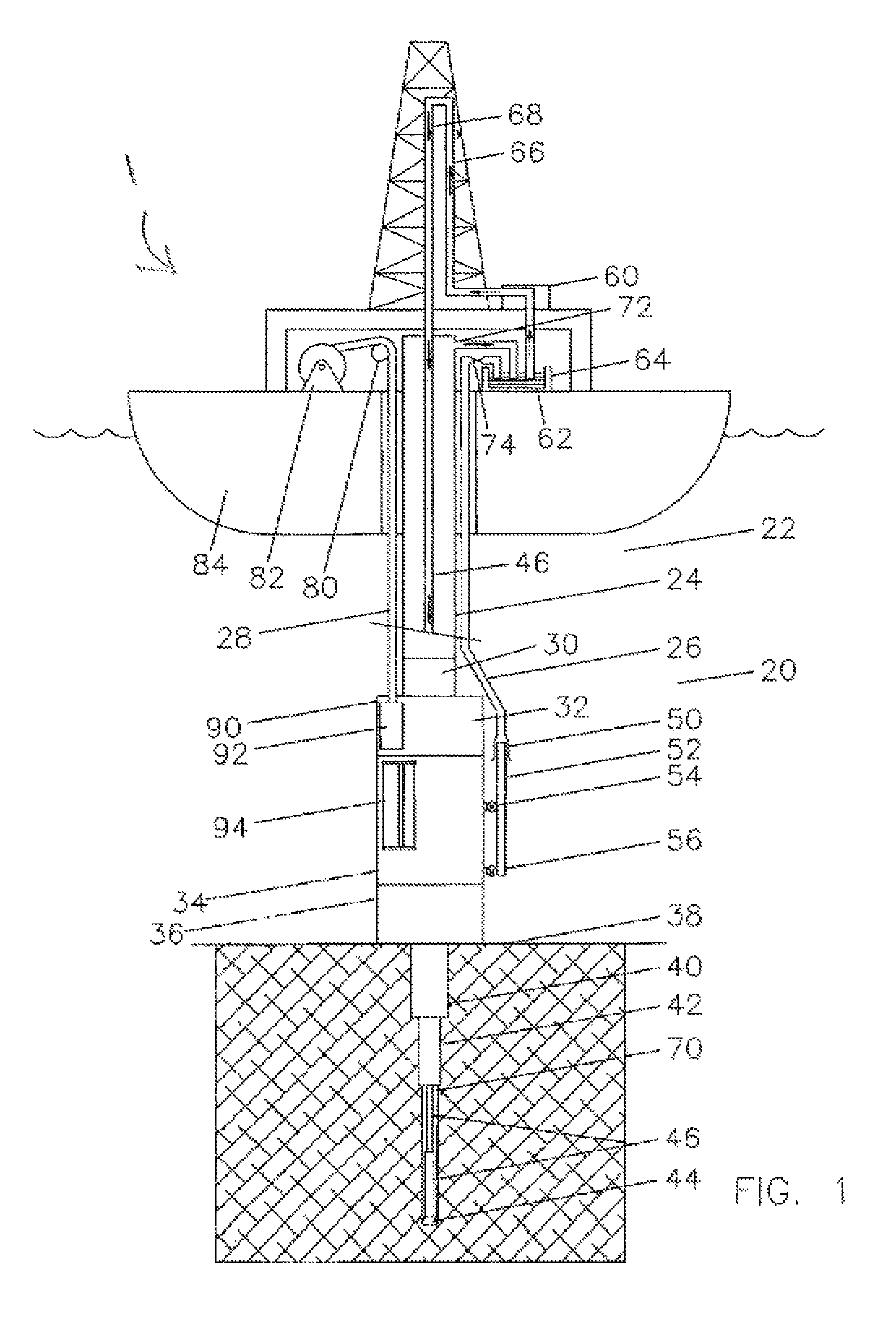
[0033]Referring to the illustrations, drawings, and pictures, and to FIG. 1 in particular, reference character 1 generally designates a new and improved reel cooling apparatus, system and method of using same constructed in accordance with the present invention. Invention 1 is generally used in reels with offshore applications but is to be understood that invention 1 may be utilized for non-offshore applications and may be utilized in other operations not associated with vessels. Invention 1 may be utilized with reels in general wherein it is desirable to cool a reel that may have undesirable heating. It is also to be understood that invention 1 may be utilized to heat a reel by utilizing warming fluids and or air instead of cooling fluids and or air where it may be desirable to heat a reel. For purposes of convenience, the reference numeral 1 may generally be utilized for the indication of the invention, portion of the invention, preferred embodiments of the invention and so on.

[00...


PUM


Abstract

A method of cooling an offshore reel with multiple layers of umbilical with heat generating electrical current flowing through internal wires by supplying a coolant through a wrap between the layers of the umbilical.

Description

BACKGROUND OF INVENTION1. Field of the Invention[0001]In general, the present invention relates to an apparatus, system and method for cooling coiled lengths positioned on a reel. More particularly, the present invention provides a new and improved reel assembly wherein unwanted heat that may be generated by electricity traveling through the coiled lengths may be cooled by providing a circulation of a coolant across and or through the reel. It is understood that the invention may further include an apparatus, system and method for heating coiled lengths by providing a circulation of heat where it may be desirable to heat the coiled lengths.2. Description of the Prior Art[0002]Electrical equipment such as dual gradient pumps is operated near the ocean floor by electrical cables or umbilicals from the surface. When this subsea equipment has high power requirements, the heat generating electrical current through the wires can be relatively high. While the cables or umbilicals are in th...

Claims


Application Information

Patent Timeline
IPC IPC(8): H01B7/42B65H49/26
CPCH01B7/423B65H49/26E21B19/22H02G11/02B65H2701/34B65H75/4478B65H2515/40B65H2601/20H01F27/085H01F27/2876F28F3/12
Inventor BAUGH, BENTON FREDERICK
Owner REEL POWER LICENSING
Why Eureka
Try Eureka