
Electronic device with improved heat dissipation capability

Active Publication Date: 2019-05-14
ACER INC
View PDF24 Cites 21 Cited by
  • Summary
  • Abstract
  • Description
  • Claims
  • Application Information

AI Technical Summary

Benefits of technology

The patent text describes an electronic device that can better manage its heat. The technical effect of this invention is improved heat dissipation, meaning the device can effectively release heat to prevent overheating and ensure better performance.

Problems solved by technology

Because the overheating of the laptop computers might result in the malfunction, cooling fans are commonly utilized to draw cooler air from and expel warmer air to the outside of the computers.
It is, however, not feasible to improve the heat dissipation by disposing many apertures on the computer chassis.
Foreign objects and moisture may easily enter the computer chassis via the apertures and damages the components of the computers.
On the other hand, the heat dissipation capability may seriously degrade without enough apertures.

Method used


Image

  • Electronic device with improved heat dissipation capability
  • Electronic device with improved heat dissipation capability
  • Electronic device with improved heat dissipation capability

Examples


Embodiment Construction

[0017]Reference will now be made in detail to the present preferred embodiments of the invention, examples of which are illustrated in the accompanying drawings. Wherever possible, the same reference numbers are used in the drawings and the description to refer to the same or like parts.

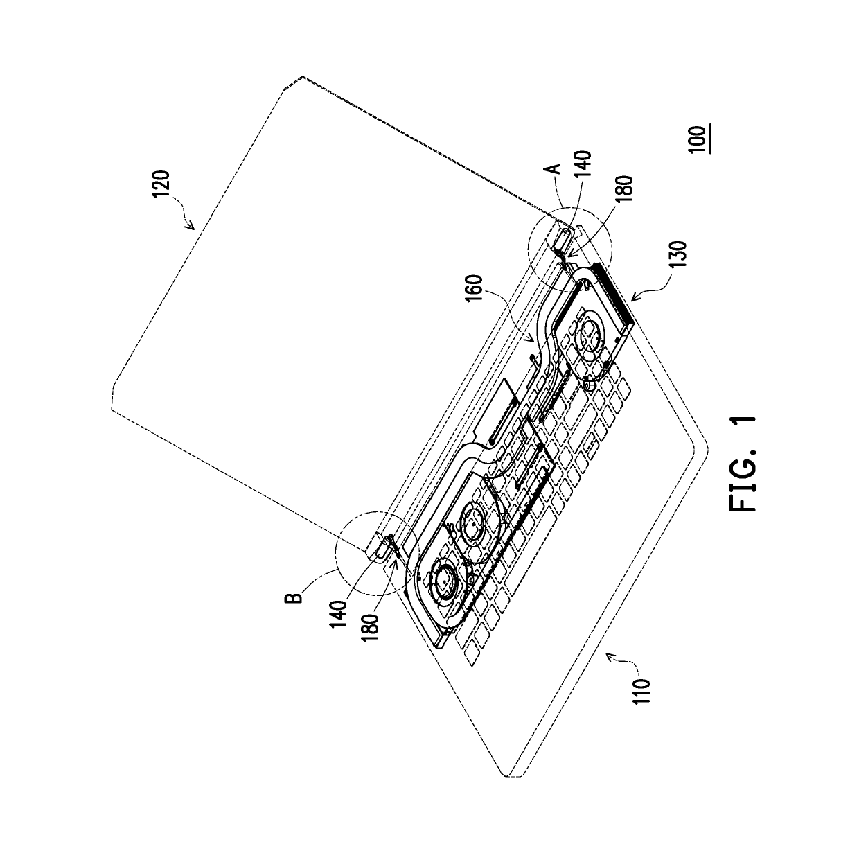
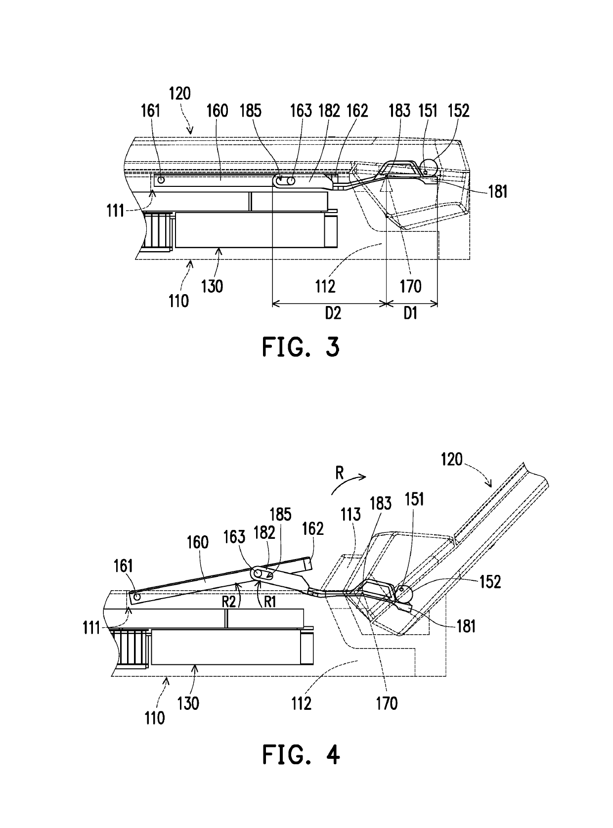
[0018]FIG. 1 is a schematic view of an electronic device according to an embodiment of the disclosure. FIG. 2 is an enlarged view of regions A and B of the electronic device of FIG. 1. It should be particularly stated that a first body 110, a second body 120 and a cover plate 160 of FIGS. 1 and 2 are drawn in broken lines to clearly demonstrate the relative relationship between respective components. Further, the electronic device 100 of FIG. 1 is in an unfolded state. In the unfolded state, an angle exists between the first body 110 and the second body 120. While in the folded state, a surface of the first body 110 substantially abuts against a surface of the second body 120.

[0019]Referring to FIGS....


PUM


Abstract

An electronic device includes a first body, a second body, a shaft, a cam, a cover plate, a fulcrum and a lever element. The first body has a convection groove. The shaft is connected to the second body. The fulcrum is connected to the shaft and disposed in the first body. The second body is pivoted to the first body through the shaft and the cam. The cover plate is movably disposed on the first body and configured to operably hide the convection groove. The fulcrum is disposed in the first body. The lever element is disposed in the first body and pivots about the fulcrum. The lever element includes a first end and a second end, respectively located at two opposite sides of the fulcrum. The cam abuts against the first end, and the second end is movably coupled to the cover plate.

Description

CROSS-REFERENCE TO RELATED APPLICATION[0001]This application claims the priority benefit of Taiwan application serial no. 107207340, filed on Jun. 1, 2018. The entirety of the above-mentioned patent application is hereby incorporated by reference herein and made a part of this specification.BACKGROUND OF THE INVENTION1. Field of the Invention[0002]The disclosure relates to an electronic device, and more particularly to an electronic device with improved heat dissipation capability.2. Description of Related Art[0003]The computing performance and the portability of laptop computers have made them indispensable for people nowadays. As the computing performance of the laptop computers keeps increasing, the heat generated by electronic components (such as a central processing unit, a graphic chip, or a display chip) operating inside the laptop computers also increases continuously. Because the overheating of the laptop computers might result in the malfunction, cooling fans are commonly ...

Claims


Application Information

Patent Timeline
IPC IPC(8): G06F1/16G06F1/20
CPCG06F1/203G06F1/206G06F1/1681G06F1/1656
Inventor CHEN, HUNG-CHICHUANG, HUEI-TINGCHEN, SHUN-BINCHUANG, KAI-YUCHIU, YEN-CHIEH
Owner ACER INC
Learn More