Permanent magnetic coupling device

Inactive Publication Date: 2015-04-02
DELTA ELECTRONICS SHANGHAI CO LTD
View PDF7 Cites 2 Cited by
  • Summary
  • Abstract
  • Description
  • Claims
  • Application Information

AI Technical Summary

Benefits of technology

The present invention provides a permanent magnetic coupling device that has improved heat dissipation capabilities. By increasing the cross-sectional area of the airflow channels between the permanent magnet rotor and the conductor rotor, the amount of air flow is increased, resulting in better heat dissipation. Furthermore, the design reduces the likelihood of demagnetization of the permanent magnets and makes the manufacturing process more convenient.

Problems solved by technology

However, the slip power of the permanent magnetic coupling device is consumed on the conductor rotor.
Once the temperature of the conductor rotor is transmitted to the permanent magnet rotor, permanent demagnetization may occur on permanent magnets of the permanent magnet rotor, thus causing malfunctioning of the permanent magnetic coupling device.
However, this solution will increase the noise of the heat dissipation blades.
Moreover, when a full load operation is performed, because the air gap is narrow to result in high wind resistance, the air flow induced by the heat dissipation blades gets weaker, thus restricting heat dissipation capability.
As to the cylindrical permanent magnetic coupling device, the air gap is at the narrowest statues during the entire rotational speed adjustment process, and heat dissipation capability is extremely restricted.
Because the sealing ring needs to replaced yearly, the maintenance cost is also high.
Meanwhile, the power is mainly consumed by the conductor ring of the conductor rotor.

Method used


Image

  • Permanent magnetic coupling device
  • Permanent magnetic coupling device
  • Permanent magnetic coupling device

Examples


first embodiment

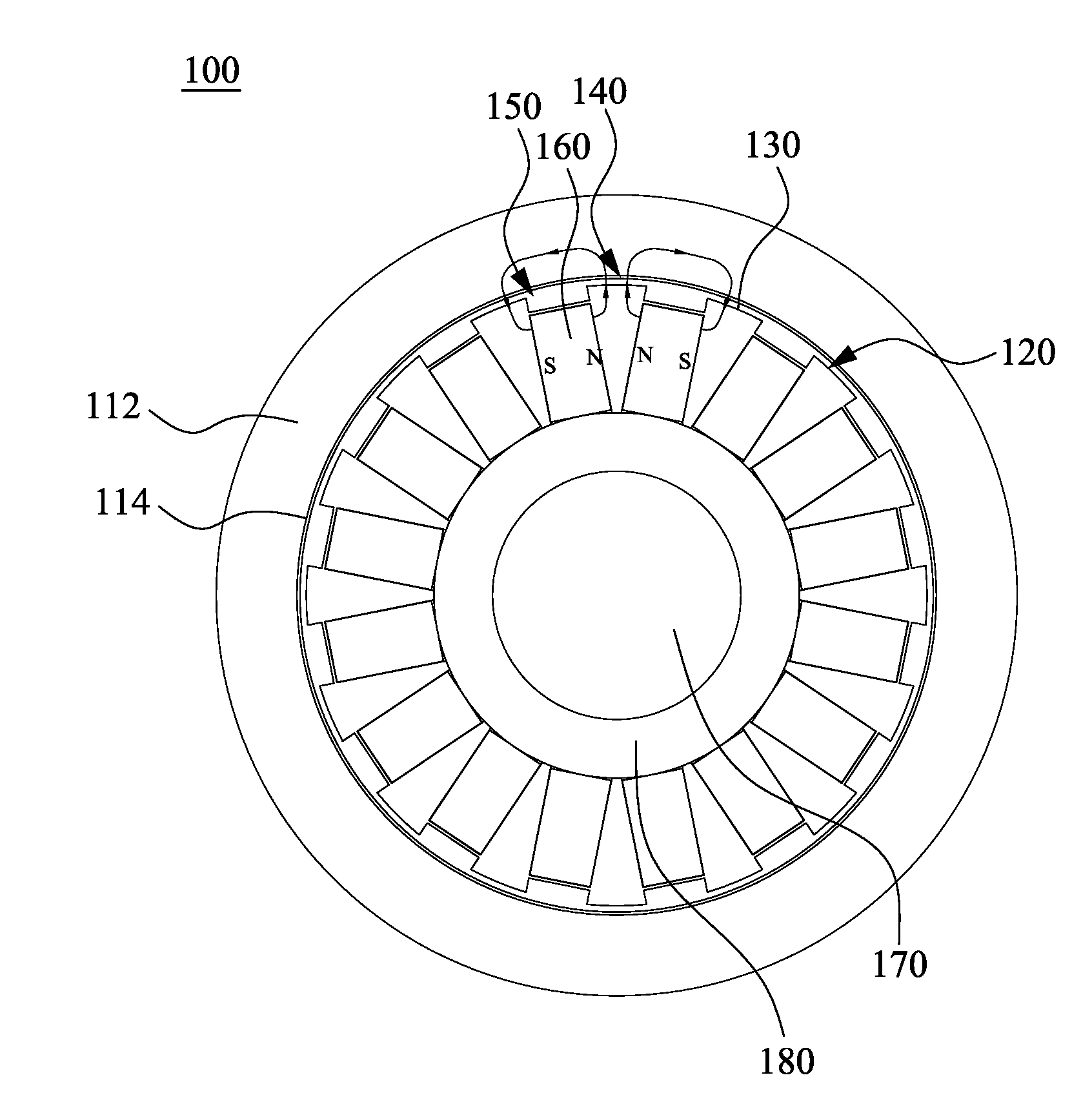
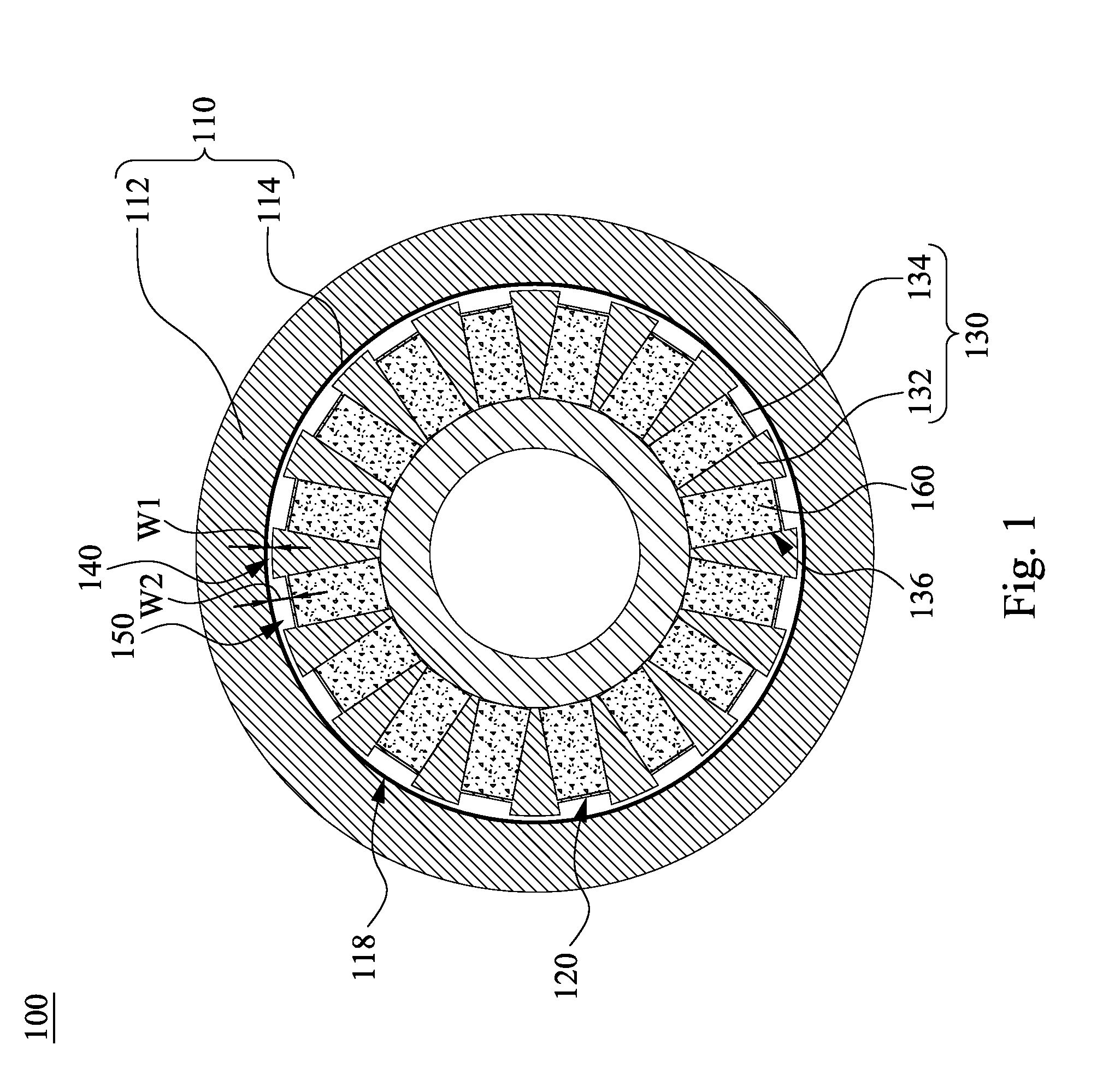
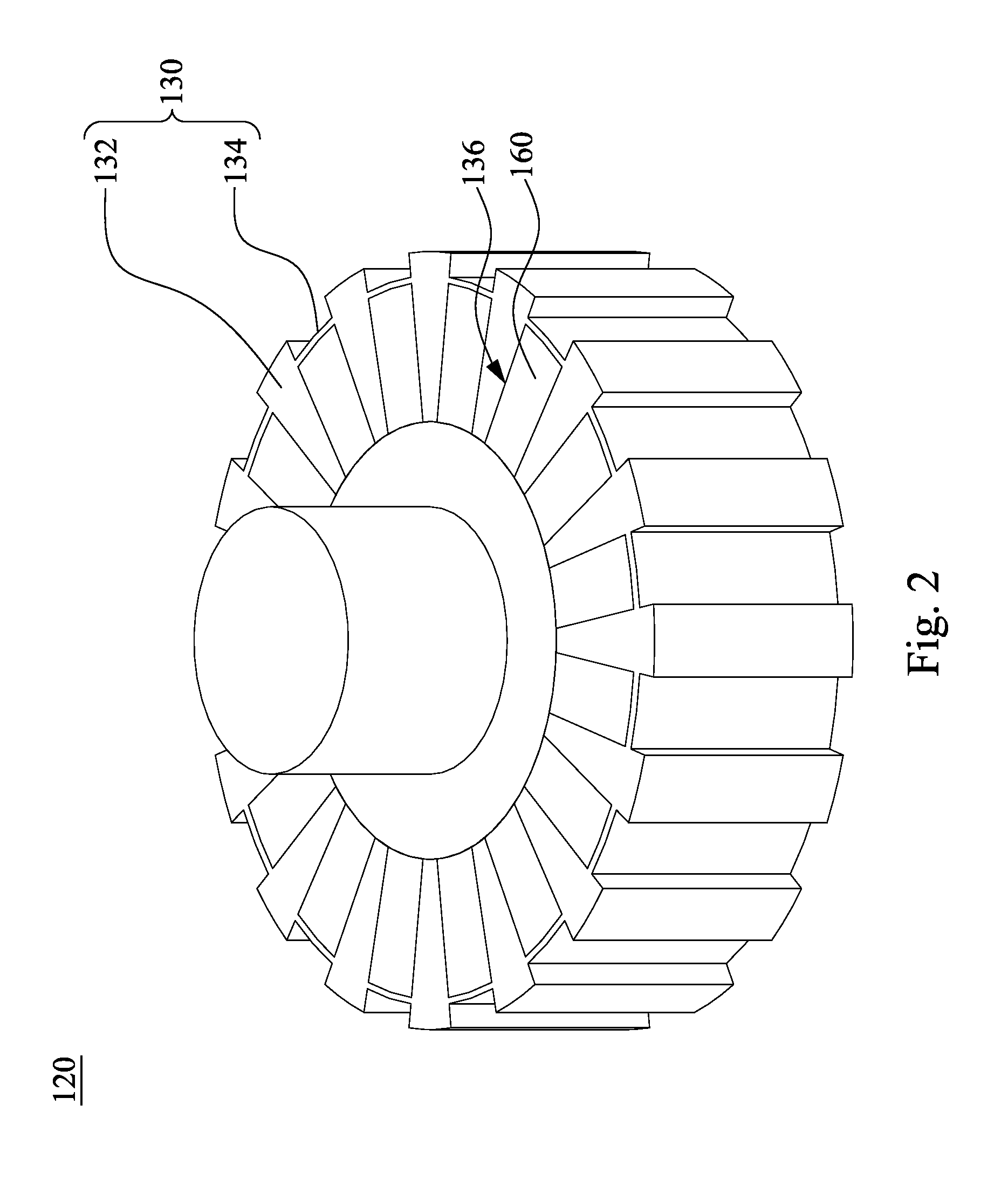
[0025]According to FIG. 1 and FIG. 2, FIG. 1 is a schematic cross-sectional diagram of a permanent magnetic coupling device 100 according to the present invention, and FIG. 2 is a schematic 3D diagram of a permanent magnet rotor in FIG. 1. The permanent magnetic coupling device 100 includes a conductor rotor 110 and a permanent magnet rotor 120, in which the permanent magnet rotor 120 includes a magnetic ring 130. The magnetic ring 130 includes protrusions 132 and recesses 134 arranged alternately. First airflow channels 140 are formed between the protrusions 132 and the conductor rotor 110 respectively, and second airflow channels 150 are formed between the recesses 134 and the conductor rotor 110 respectively. A cross-sectional area of each of the second airflow channels 150 is greater than a cross-sectional area of each of the first airflow channels 140. A width of the each of the first airflow channels 140 W1 is in a range from 2 mm to 8 mm, and a width of the each of the second...

second embodiment

[0036]FIG. 6 is a cross-sectional schematic view of a permanent magnetic rotor according to the present invention. A permanent magnet rotor 220 includes a magnetic ring 230 including protrusions 232 and recesses 234 which are arranged alternately. First airflow channels are formed between the protrusions 232 and the conductor rotor (refer to the FIG. 1) respectively, and second airflow channels 250 are formed between the recesses 234 and the conductor rotor respectively. A cross-sectional area of each of the second airflow channels 250 is greater than a cross-sectional area of each of the first airflow channels.

[0037]The magnetic ring 230 connects to a load shaft 270. The magnetic ring 230 further includes magnetic bridges 236 disposed between the load shaft 270 and the protrusions 232. The magnetic ring 230 further includes a magnetic inner ring 238 fixed on the load shaft 270. The magnetic inner ring 238 and the protrusions 232 are connected through the magnetic bridges 236 such t...

third embodiment

[0040]FIG. 7 is a schematic 3D diagram of a permanent magnetic rotor according to the present invention. A permanent magnet rotor 320 includes a magnetic ring 330, and the magnetic ring 330 includes protrusions 332 and recesses 334 arranged alternately. First airflow channels are formed between the protrusions 332 and the conductor rotor (referring to FIG. 1), and second airflow channels 350 are formed between the recesses 334 and the conductor rotor. A cross-sectional area of each of the second airflow channels 350 is greater than a cross-sectional area of each of the first airflow channels. Permanent magnets 360 are engaged in cavities 336 disposed in the recesses 334.

[0041]In the present embodiment, the protrusions 332 and the recesses 334 are approximately parallel to each other. An angle θ is defined between the protrusions 332, the recesses 334 or the second airflow channel 350 and an axial direction of the permanent magnet rotor 320. The angle θ is from 0 to 240 / p degrees, in...


PUM


Abstract

A permanent magnetic coupling device includes an conductor rotor, an permanent magnet rotor and permanent magnets. The permanent magnet rotor includes a magnetic ring. The magnetic ring includes protrusions and recesses arranged alternately, in which first airflow channels are formed between the protrusions and the conductor rotor respectively, and second airflow channels are formed between the recesses and the conductor rotor respectively. A cross-sectional area of each of the second airflow channels is greater than a cross-sectional area of each of the first airflow channels. The permanent magnet rotor further includes cavities disposed at the recesses, and the permanent magnets are engaged into the cavities respectively.

Description

RELATED APPLICATIONS[0001]This application claims priority to China Application Serial Number 201310461605.6, filed Sep. 30, 2013, which is herein incorporated by reference.BACKGROUND[0002]1. Field of Invention[0003]The present invention relates to a permanent magnetic coupling device. More particularly, the present invention relates to a permanent magnetic coupling device with wider airflow channels.[0004]2. Description of Related Art[0005]A permanent magnetic coupling device is a transmission device that transmits torque through an air gap. The permanent magnetic coupling device includes an conductor rotor and an permanent magnet rotor. The conductor rotor is fixed on an active shaft and connected to a motor. The permanent magnet rotor is fixed on a load shaft and connected to a load. An air gap is formed between the conductor rotor and the permanent magnet rotor, such that a connection between the motor and the load can be changed from a mechanical connection to a magnetic connec...

Claims


Application Information

Patent Timeline
IPC IPC(8): H01F7/02
CPCH01F7/021H01F7/0242
Inventor ZHU, HONG-LIUAI, TSU-HUASHEU, HONG-CHENG
Owner DELTA ELECTRONICS SHANGHAI CO LTD
Why Eureka
Try Eureka