Fuel tank with carbon dioxide storage

a technology of carbon dioxide storage and fuel tanks, which is applied in the direction of liquid fuel feeders, machines/engines, separation processes, etc., can solve the problems of insufficient co2 in the atmosphere, but the effect of helping

Active Publication Date: 2019-05-07
VANDERHALL MOTOR WORKS INC
View PDF27 Cites 1 Cited by
  • Summary
  • Abstract
  • Description
  • Claims
  • Application Information

AI Technical Summary

Benefits of technology

[0012]The CO2 removal process may include parallel and series CO2 scrubbers and / or CO2 membranes to achieve a desired purity and throughput of a vehicle's exhaust system. A vehicle's exhaust system may provide less than 50 part per million CO2 in its exhaust gas after going through one or more scrubbing and / or membrane filtering processes. One or more sensors may determine a part per million count of CO2 in a pre and post exhaust gas processing in order to configure one or more CO2 removal systems for optimal operation based on vehicle speed, combustion air quality, type of fuel, vehicle performance, and CO2 storage levels within a CO2 storage area. A CO2 removal system may include one or more scrubber systems, membrane systems, heat exchange systems, compressor systems, and condenser systems. Compressor systems may need to have one or more compressor stages to reach a desired pressure and volume. Heat exchange systems may need to have heating and cooling capacity provided by a thermal electric module or Peltier module. Heat exchange systems may also be dynamically configured to increase or decrease surface area to achieve a desired temperature and throughput. Scrubber systems may include one or more parallel or series treatment regions or surfaces which may be dynamically configured based on CO2 sensor feedback. Membrane systems may be included within a scrubber or be a separate system providing CO2 filtering. A number of membranes and / or surface area exposure may be dynamically configured to achieve a desired CO2 throughput and purity. An expansion tank may be used to stage and cool exhaust gas as it leaves an engine before processing by a scrubber system. An expansion tank system may allow for accumulation of exhaust gas over a process threshold of the scrubber system. A pre-cooling system may be used to cool exhaust as it leaves the engine. The pre-cooling system may be air cooled, water cooled, or thermal electrically cooled.
[0013]A CO2 filter may be used in conjunction with the recovered CO2 to increase a purity factor of the stored CO2. Removable CO2 storage tanks may be used in addition to CO2 stored in a fuel tank or as a standalone CO2 storage.

Problems solved by technology

Regulation of motor vehicle standards is helpful but not sufficient to stop the yearly increasing levels of CO2 in the atmosphere.

Method used


Image

  • Fuel tank with carbon dioxide storage
  • Fuel tank with carbon dioxide storage
  • Fuel tank with carbon dioxide storage

Examples


Embodiment Construction

[0028]It will be readily understood that the components of the present invention, as generally described and illustrated in the Figures herein, may be arranged and designed in a wide variety of different configurations. Thus, the following more detailed description of the embodiments of the invention, as represented in the Figures, is not intended to limit the scope of the invention, as claimed, but is merely representative of certain examples of presently contemplated embodiments in accordance with the invention.

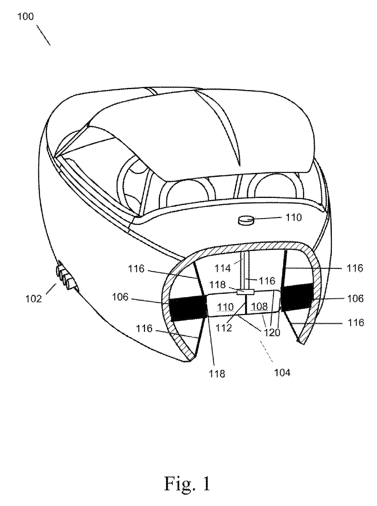
[0029]FIG. 1 shows a vehicle 100 which collects CO2 and / or other exhaust components in area 110 of fuel tank 104. Fuel tank 104 includes two storage areas 108 and 110. Storage area 108 may store a combustible fuel such as gasoline, diesel fuel, liquefied petroleum gas, liquefied natural gas, compressed natural gas, alcohol, butane, or hydrogen. The fuel stored in area 108 may be a compressed gas fuel or a liquid fuel. Storage area 110 may store compressed gas or liquefied g...


PUM


Abstract

A fuel tank and a motor vehicle equipped to recapture, store and recycle atmospheric carbon dioxide is disclosed. In one embodiment, such a vehicle includes a fuel tank which stores carbon dioxide in a same area with the combustible fuel of the vehicle. The fuel tank may include one or more pistons, baffles, bladders, or fixed dividers to separate carbon dioxide storage from fuel storage within a fuel tank area. The fuel tank may share volumetric space between carbon dioxide and fuel within the fuel tank. The fuel tank may be integrally formed into a carbon fiber vehicle body. The fuel tank may be integrally formed into a frame of a vehicle.

Description

BACKGROUND[0001]Field of the Invention[0002]This invention relates to recapture, storage and recycling of atmospheric carbon dioxide (CO2) using a vehicle and a vehicle fuel tank.[0003]Background of the Invention[0004]Carbon dioxide (CO2) is the primary greenhouse gas emitted through human activities. The main human activity that emits CO2 is the combustion of fossil fuels (coal, natural gas, and oil) for energy and transportation.[0005]The combustion of fossil fuels such as gasoline and diesel to transport people and goods is the second largest source of CO2 emissions, accounting for about 31% of total U.S. CO2 emissions. This category includes transportation sources such as highway vehicles, air travel, marine transportation, and rail.[0006]Carbon dioxide emissions in the United States increased by about 7% between 1990 and 2013. Since the combustion of fossil fuel is the largest source of greenhouse gas emissions in the United States, changes in emissions from fossil fuel combust...

Claims


Application Information

Patent Timeline
Patent Type & Authority Patents(United States)
IPC IPC(8): B01D53/22B01D53/62B60K13/04F02M37/00F02M21/02B60K15/03
CPCF02M37/0088B01D53/62B60K13/04F02M21/0206F02M21/0296B60K15/03B60K2015/03078B60K2015/0344B01D53/22B01D53/92B01D2257/504Y02C20/40
Inventor HALL, DAVID R.HALL, STEPHEN R.
Owner VANDERHALL MOTOR WORKS INC
Why Eureka
Try Eureka