
Utility knife with pivoting head assembly

a technology of pivoting head and utility knife, which is applied in the field of utility knife, can solve the problems of large cutting force, difficult to use the knife in tight spaces, and the right-handed user may be forced to use his/her left (weaker) hand to make a cut, etc., and achieves the effects of being easy to use in tight spaces, rigid, and rigid

Inactive Publication Date: 2019-05-07
GILBERT JAMES +2
View PDF15 Cites 1 Cited by
  • Summary
  • Abstract
  • Description
  • Claims
  • Application Information

AI Technical Summary

Benefits of technology

[0008]Accordingly, it is an object of the invention to provide a durable utility knife that is extremely rigid in construction. It is a further object of the invention to provide a rigid, durable utility knife that can be easily utilized in tight spaces, such as at a cabinet toe kick or other surfaces that are difficult to reach. It is a further object of the invention to provide a durable utility knife that has a blade head assembly that can pivot transversely with respect to the knife handle body assembly.
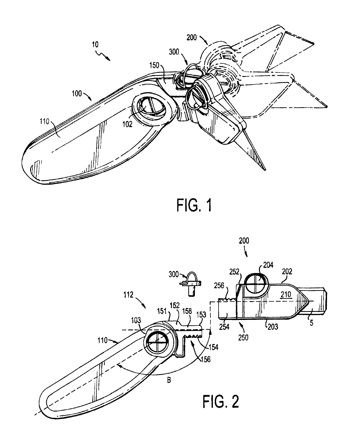
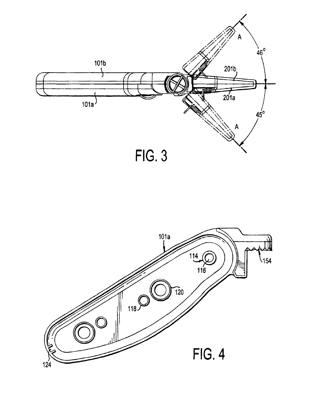
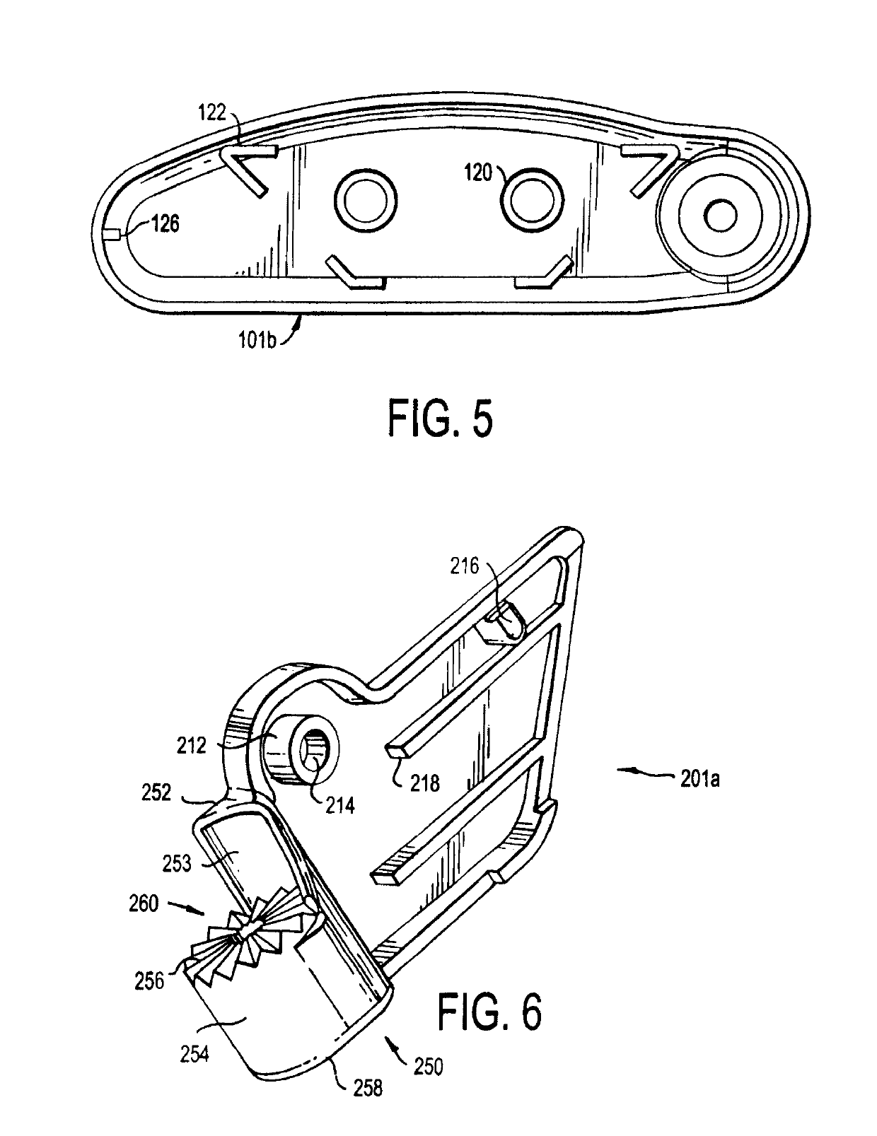
[0009]A utility knife is provided that has an elongated main body portion and a head assembly that is separate from the main body portion. The main body portion has a handle assembly. A main body fastening mechanism is provided at one distal end of the handle assembly, and a handle assembly fastening mechanism is provided at one end of the handle assembly. A threaded pin pivotally fastens the main body portion to the head assembly by connecting the main body fastening mechanism to the handle assembly fastening mechanism. Accordingly, the head assembly can pivot with respect to the main body portion and handle assembly, so that the utility knife can be configured to fit in a tight cutting space.

Problems solved by technology

This makes the knife extremely durable and enables a large force to be applied to the knife by the user, resulting in a large cutting force.
However, the knife is difficult to use in tight spaces, especially when a large cutting force is still needed.
As a result, a right-handed user may be forced to use his / her left (weaker) hand to make a cut.
However, the obstacles do not always allow for sufficient space to make a clean cut, and it can be difficult or impossible for the utility knife to fit in a tight space.
In particular, obstacles having recessed bottom surfaces, such as furniture and cabinetry, which can present significant challenges to obtaining a proper carpet cut and can slow work.

Method used


Image

  • Utility knife with pivoting head assembly
  • Utility knife with pivoting head assembly
  • Utility knife with pivoting head assembly

Examples


Embodiment Construction

[0029]In describing a preferred embodiment of the invention illustrated in the drawings, specific terminology will be resorted to for the sake of clarity. However, the invention is not intended to be limited to the specific terms so selected, and it is to be understood that each specific term includes all technical equivalents that operate in similar manner to accomplish a similar purpose. Several preferred embodiments of the invention are described for illustrative purposes, it being understood that the invention may be embodied in other forms not specifically shown in the drawings.

[0030]Referring to the drawings. FIG. 1 shows a box cutter or utility knife 10 in accordance with a non-limiting example of the preferred invention. The utility knife 10 has a main body 100 and a head assembly 200, which are pivotally connected together at a fastening mechanism 300. The main body 100 includes a handle assembly 110 that is elongated and has a longitudinal axis. The handle assembly 110 is ...


PUM


Abstract

A utility knife is provided that has an elongated main body portion and a head assembly that is separate from the main body portion. The main body portion has a handle assembly. A main body fastening mechanism is provided at one distal end of the handle assembly, and a handle assembly fastening mechanism is provided at one end of the handle assembly. A threaded pin pivotally fastens the main body portion to the head assembly by connecting the main body fastening mechanism to the handle assembly fastening mechanism. Accordingly, the head assembly can pivot with respect to the main body portion and handle assembly, so that the utility knife can be configured to cut an object at different angles, which can be particularly useful for the knife to fit in a tight cutting space.

Description

RELATED APPLICATIONS[0001]This application is a continuation-in-part of U.S. Design patent application Ser. No. 29 / 517,346, filed Feb. 12, 2015, and a continuation-in-part of U.S. patent application Ser. No. 14 / 157,187, filed Jan. 16, 2014, which is a continuation-in-part of U.S. patent application Ser. No. 13 / 797,036, filed Mar. 12, 2013, which claims the benefit of U.S. Provisional Application No. 61 / 681,461, filed Aug. 9, 2012. The entire contents of each of those applications is incorporated herein by reference.BACKGROUND OF THE INVENTION[0002]Field of the Invention[0003]The present invention relates to a utility knife. More particularly, the present invention relates to a utility knife that can pivot to enable use in different angles and / or to fit into tight spaces.[0004]Background of the Related Art[0005]Utility knifes are used for a variety of general or utility purposes. Utility knifes can have a number of features, including a retractable blade, replaceable blades, blade st...

Claims


Application Information

Patent Timeline
Patent Type & Authority Patents(United States)
IPC IPC(8): B26B1/08B26B1/10
CPCB26B1/08B26B1/10B26B5/00B26B5/005
Inventor GILBERT, JAMESMARSHALL, MICHAEL L.MOYA, PAOLA
Owner GILBERT JAMES
Learn More