Electric connector

a technology of electric connectors and connectors, applied in the direction of semiconductor devices, electrical equipment, semiconductor/solid-state device details, etc., can solve the problems of difficult to avoid, electronic devices or systems being shut down, and damage to electronic devices or systems, so as to avoid permanent broken circuits caused by burning out the second vertical element, the effect of increasing the lifetime of the formed electronic devi

Active Publication Date: 2019-04-16
UNITED MICROELECTRONICS CORP
View PDF3 Cites 1 Cited by
  • Summary
  • Abstract
  • Description
  • Claims
  • Application Information

AI Technical Summary

Benefits of technology

[0006]The present invention provides an electric connector, which sets the partial maximum current load of the electric connector to restrain the burning point of the electric connector, thereby preventing the whole circuit from working failure, and thus increasing the lifetime of a formed electronic device.
[0009]According to the above, the present invention provides an electric connector, which has a first vertical element connected to a top surface of a horizontal element, and a second vertical element connected to a bottom surface of the horizontal element. While a voltage higher than a specific voltage is applied, the horizontal element or the above first vertical element is burned out before the second vertical element below the horizontal element is burned out, thereby a short circuit occurring before the second vertical element is burned out. Therefore, a permanent broken circuit caused by burning out the second vertical element can be avoided. Hence, this increases the lifetime of a formed electronic device including the electric connector.

Problems solved by technology

Electrostatic Discharge (ESD) causes electronic devices or systems being damaged due to Electrical Overstress (EOS).
Permanent damage of electronic devices or systems occurs by this damage, thus affecting the functions of Integrated Circuits (ICs) of the electronic devices or systems, leading to the electronic devices or systems shutting down.
Anthropic factors are the main reason to make Electrostatic Discharge (ESD) occur, but they are difficult to be avoided.

Method used


Image

  • Electric connector
  • Electric connector
  • Electric connector

Examples


Embodiment Construction

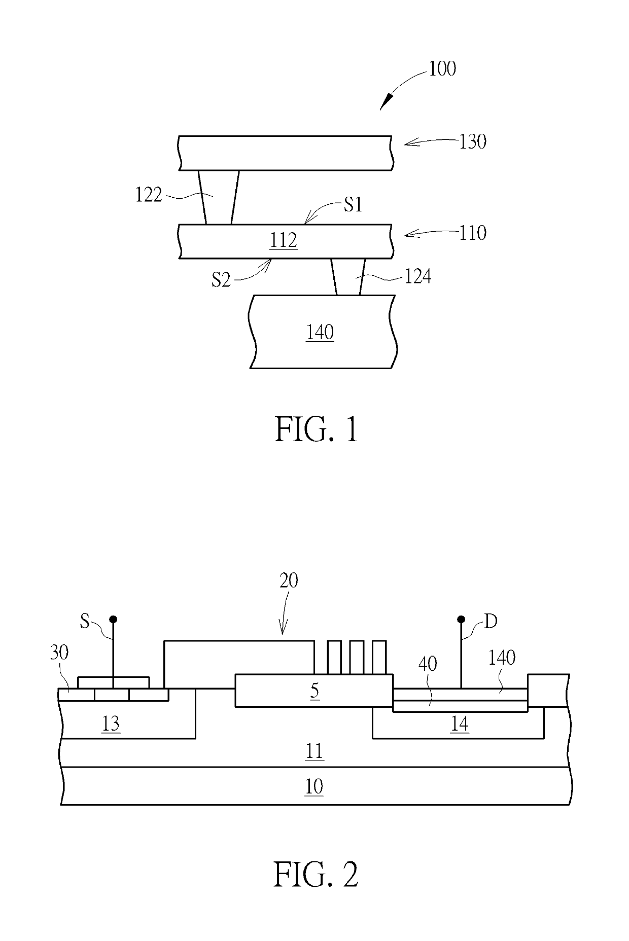
[0016]FIG. 1 schematically depicts a cross-sectional view of an electric connector according to an embodiment of the present invention. As shown in FIG. 1, an electric connector 100 may include a metal interconnect 110, and the metal interconnect 110 may include a horizontal element 112. FIG. 1 is a cross-sectional view of an electric connector, thereby only one horizontal element 112 being depicted, but there may be a plurality of horizontal elements 112 arranged along a direction toward the paper. Atop surface S1 of each of the horizontal elements 112 physically connects to a first vertical element 122, and a bottom surface S2 of each of the horizontal elements 112 physically connects to a second vertical element 124.

[0017]The horizontal element 112, the first vertical element 122 and the second vertical element 124 are composed of metals such as copper, aluminum or tungsten etc. In this embodiment, the metal interconnect 110 includes a first metal layer, and thus the first vertic...


PUM


Abstract

An electric connector includes a metal interconnect, a first vertical element and a second vertical element. The metal interconnect includes a plurality of horizontal elements. The first vertical element physically connects to a top surface of each of the horizontal elements. The second vertical element physically connects to a bottom surface of each of the horizontal elements, and the second vertical element misaligns the first vertical element. The present invention also provides an electric connector including a first vertical element and a second vertical element. The first vertical element physically connects to a top surface of a horizontal element. The second vertical element physically connects to a bottom surface of the horizontal element, and the second vertical element misaligns the first vertical element, wherein the first vertical element or the horizontal element is burned out before the second vertical element is burned out while a voltage is applied.

Description

BACKGROUND OF THE INVENTION[0001]1. Field of the Invention[0002]The present invention relates generally to an electric connector, and more specifically to an electric connector connecting metal interconnects.[0003]2. Description of the Prior Art[0004]Electrostatic Discharge (ESD) causes electronic devices or systems being damaged due to Electrical Overstress (EOS). Permanent damage of electronic devices or systems occurs by this damage, thus affecting the functions of Integrated Circuits (ICs) of the electronic devices or systems, leading to the electronic devices or systems shutting down. Anthropic factors are the main reason to make Electrostatic Discharge (ESD) occur, but they are difficult to be avoided. Electrostatic charges are accumulated in human bodies, instruments, storage equipment or etc. while manufacturing, producing, assembling, testing, storing or moving these electronic devices or systems (even these electronic devices or systems accumulate electrostatic charges the...

Claims


Application Information

Patent Timeline
Patent Type & Authority Patents(United States)
IPC IPC(8): H01L23/52H01L23/525H01L23/522
CPCH01L23/5223H01L23/5256H01L23/535H01L23/62H01L27/0203H01L27/0292
Inventor WANG, JHIH-MINGWANG, LI-CIHTANG, TIEN-HAO
Owner UNITED MICROELECTRONICS CORP
Why Eureka
Try Eureka