Textile machine

A textile machine and spinning technology, applied in the field of spinning cover, can solve problems such as affecting the quality of yarn

Inactive Publication Date: 2020-12-15
SAURER INTELLIGENT TECH AG
View PDF7 Cites 0 Cited by
  • Summary
  • Abstract
  • Description
  • Claims
  • Application Information

AI Technical Summary

Problems solved by technology

Dirt such as dirt particles, wax, oil, etc. in the surroundings of the inlet can be smoothly fed into the inlet with the fiber material and adversely affect the yarn quality

Method used


Image

  • Textile machine
  • Textile machine
  • Textile machine

Examples


Embodiment Construction

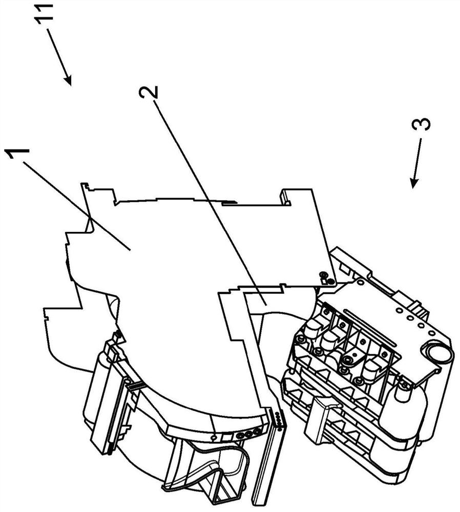
[0044] exist figure 1 A spinning device 11 of a textile machine (not shown here) having a spinning unit designed as an air spinning unit 1 is shown in FIG. The strand-shaped fiber material, not shown here, is conveyed to the inlet of the spinning nozzle by means of the delivery roller pair of the drafting device 3 of the spinning device 11, which is arranged in the spinning direction in front of the spinning nozzle of the air spinning unit 1. And from there it is sucked or sucked in by negative pressure.

[0045] The spinning hood 2 of the spinning device 11 in the working position is arranged in the region between the drafting device 3 and the rotor spinning unit 1 . The spinning hood 2 delimits the spinning space around the inlet with respect to the surroundings, where the spinning hood adjoins the drafting device 3 and the rotor spinning unit 1 for this purpose without hindering the fiber sliver from the drafting device 3 was sent into the entrance.

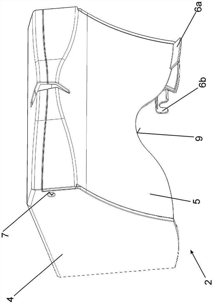
[0046] exist figure...


PUM


Abstract

The invention relates to a textile machine having a plurality of spinning devices, more particularly air-jet spinning devices, which spinning devices have an inlet opening for a fiber band to be spun,and to a spinning hood for a spinning device of a textile machine. In order to provide a textile machine comprising a plurality of spinning devices, which have an inlet opening for a fiber band to bespun and in the case of which the feeding of contaminants into the inlet opening is prevented as much as possible, there is provision for a spinning hood to be provided, which is designed in such a way that the spinning hood separates a spinning space around an inlet opening of the spinning device from the surroundings.

Description

technical field [0001] The invention relates to a textile machine with a plurality of spinning devices, in particular rotor spinning yarn device. Background technique [0002] A textile machine of the type mentioned in the introduction has a plurality of spinning devices for the production of yarn, to which fiber material is supplied, where the fiber material fed to the spinning devices is formed into a yarn by means of the spinning devices, the yarn passing through the outlet It leaves the spinning device, where it is wound up on a bobbin by means of a winding device. [0003] The spinning device of this type of textile machine can be designed, for example, as an open-end spinning machine, where the production of yarn from strand-shaped fiber material (such as fiber slivers) takes place by means of a swirling air flow generated in a swirling chamber by means of air nozzles. . For this purpose, the strip-shaped fiber material is fed to the inlet of the spinning nozzle by ...

Claims


Application Information

Patent Timeline
Patent Type & Authority Applications(China)
IPC IPC(8): D01H5/16D01H4/02
CPCD01H4/02D01H5/16D01H1/16D01H1/115D01H4/38
Inventor J·德雷森E·普雷迪格尔
Owner SAURER INTELLIGENT TECH AG
Why Eureka
Try Eureka