Pressure-type flow rate control device
a flow rate control and flow rate technology, applied in the direction of diaphragm valves, valve housings, instruments, etc., can solve the problems of difficult to significantly low gas replaceability, and low so-called gas shutoff responsiveness, so as to improve the shutoff response characteristics and reduce the distance between the control valve for pressure control and the on/off valve , the effect of improving the shutoff characteristics
- Summary
- Abstract
- Description
- Claims
- Application Information
AI Technical Summary
Benefits of technology
Problems solved by technology
Method used
Image
Examples
first embodiment
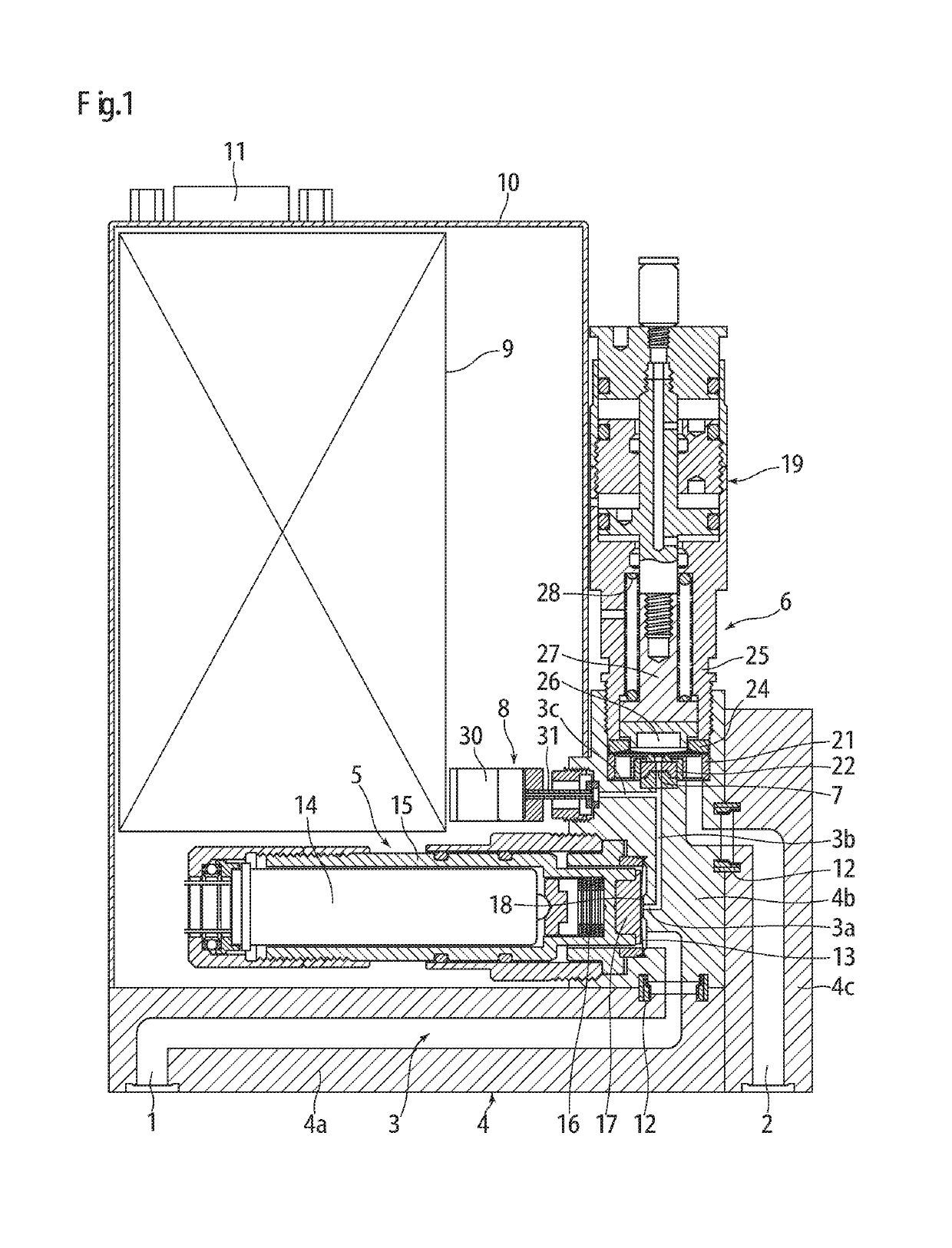
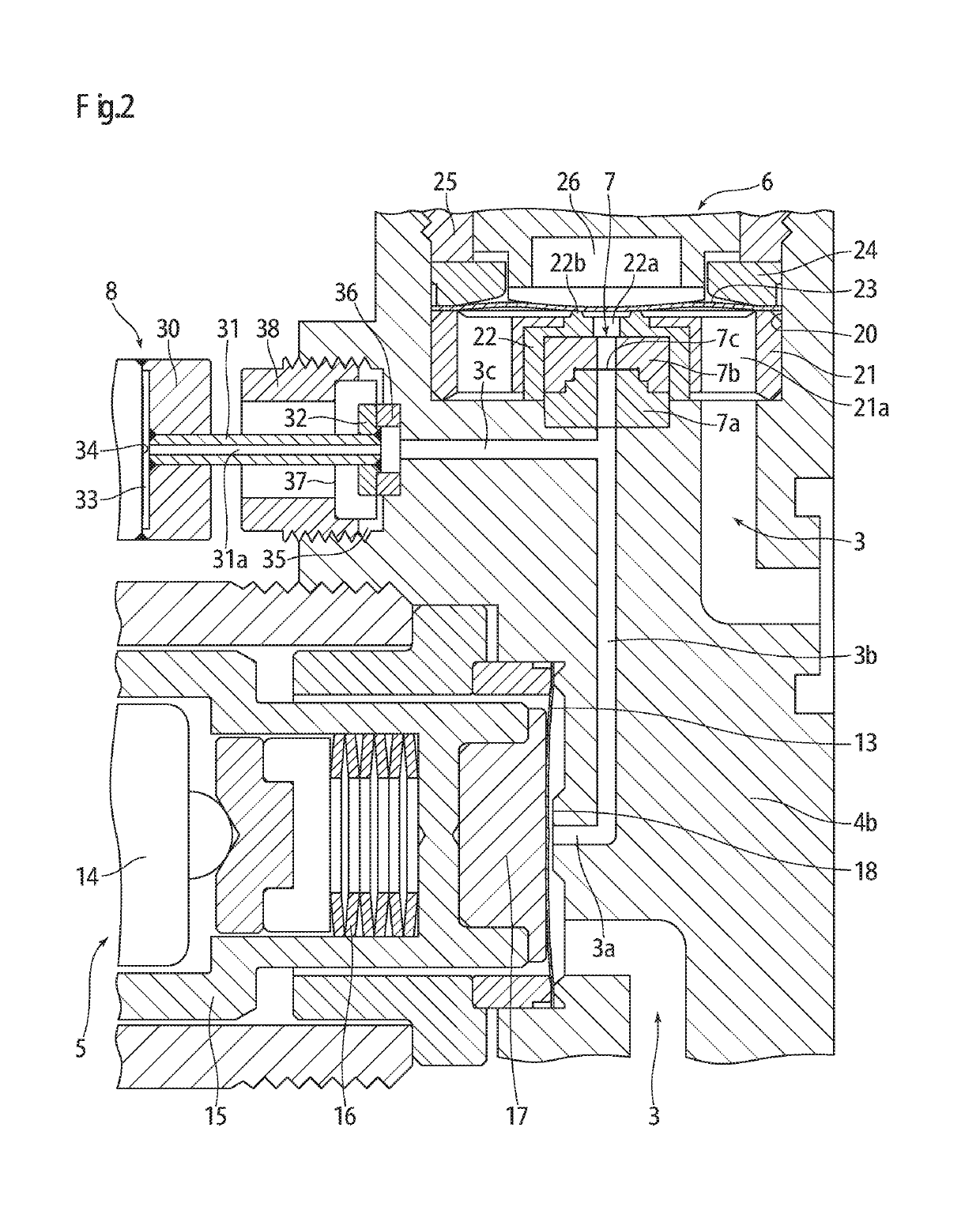
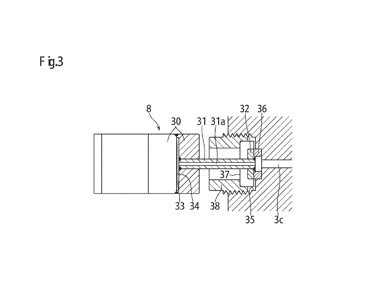
[0076]FIG. 1 and FIG. 2 show a pressure-type flow controller according to the present invention. The pressure-type flow controller includes: a main body 4 provided with a fluid passage 3 communicating between a fluid inlet 1 and a fluid outlet 2; a control valve for pressure control 5 fixed in a horizontal position to the main body 4 for opening / closing the fluid passage 3; an on / off valve 6 fixed in a vertical position to the main body 4 for opening / closing the fluid passage 3 on the downstream side of the control valve for pressure control 5; an orifice 7 provided in the fluid passage 3 on the upstream side of the on / off valve 6; and a pressure sensor 8 fixed to the main body 4 for detecting the internal pressure of the fluid passage 3 between the control valve for pressure control 5 and the orifice 7. The fluid passage 3 includes: a first passage portion 3a in a horizontal position connected to the control valve for pressure control 5; a second passage portion 3b in a vertical po...
second embodiment
[0100]FIG. 4 and FIG. 5 show a pressure-type flow controller according to the present invention. The pressure-type flow controller includes: a main body 4 provided with a fluid passage 3 communicating between a fluid inlet 1 and a fluid outlet 2; a control valve for pressure control 5 fixed in a horizontal position to the main body 4 for opening / closing the fluid passage 3; an on / off valve 6 fixed to the main body 4 to be opposed to the control valve for pressure control 5 for opening / closing the fluid passage 3 on the downstream side of the control valve for pressure control 5; an orifice 7 provided in the fluid passage 3 on the upstream side of the on / off valve 6; and a pressure sensor 8 fixed to the main body 4 for detecting the internal pressure of the fluid passage 3 between the control valve for pressure control 5 and the orifice 7. The fluid passage 3 includes: a horizontal passage portion 3d connecting between the control valve for pressure control 7 and the orifice 7; and a...
third embodiment
[0118]FIG. 6 shows a pressure-type flow controller according to the present invention. In the pressure-type flow controller, a fluid inlet 1 and a fluid outlet 2 are formed on the same surface of a main body 4 (upper surface of the main body 4 shown in FIG. 6) such that the fluid inlet 1 and the fluid outlet 2 are arranged in one direction on the main body 4. At the same time, a pressure sensor 8 is provided at a central position of the surface of the main body 4 on the opposite side of the fluid inlet 1 and the fluid outlet 2 (lower surface of the main body 4 shown in FIG. 6).
[0119]Except that the fluid inlet 1 and the fluid outlet 2 are formed on the same surface of the main body 4, and that the pressure sensor 8 is provided at the central position of the opposite surface of the main body 4, the pressure-type flow controller according to the third embodiment is configured to have the same structure as the pressure-type flow controller according to the second embodiment shown in FI...
PUM
 Abstract
Description
Claims
Application Information
 - R&D
- Intellectual Property
- Life Sciences
- Materials
- Tech Scout
- Unparalleled Data Quality
- Higher Quality Content
- 60% Fewer Hallucinations
Browse by: Latest US Patents, China's latest patents, Technical Efficacy Thesaurus, Application Domain, Technology Topic, Popular Technical Reports.
© 2025 PatSnap. All rights reserved.Legal|Privacy policy|Modern Slavery Act Transparency Statement|Sitemap|About US| Contact US: help@patsnap.com


