
Numerical controller and simulator thereof

a numerical controller and simulator technology, applied in the direction of program control, electric programme control, instruments, etc., can solve the problems of inability to perform machining of an appropriate cut depth, inability to efficiently increase the working speed of the lathe, and inability to create machining programs for issuing commands to the two or more paths. , to achieve the effect of increasing the speed of machining

Active Publication Date: 2019-04-09
FANUC LTD
View PDF22 Cites 0 Cited by
  • Summary
  • Abstract
  • Description
  • Claims
  • Application Information

AI Technical Summary

Benefits of technology

The invention provides a numerical controller that can efficiently increase the speed of machining by controlling multiple paths using a single program. The controller automatically assigns cutting motion commands to multiple paths, allowing the operator to increase the speed of machining without needing to create separate cutting programs for each path.

Problems solved by technology

Creating machining programs for issuing commands to the two or more paths takes a lot of effort.
However, even if a machining program for two or more paths is generated by such a method, there is a problem that the machining speed of lathe working cannot be efficiently increased.
Accordingly, in the case where these machining steps are assigned to different paths and where an attempt to perform the machining steps at the same time is made, when machining by the second machining step is performed at a position on the workpiece where machining by the first machining step has not been performed yet, machining of an appropriate cut depth cannot be performed, and there occur the following problems: the tool or a servo motor for driving the tool is heavily loaded, the quality of a machined surface is deteriorated, or the like.
Accordingly, the speed of machining cannot be efficiently increased using two or more paths.

Method used


Image

  • Numerical controller and simulator thereof
  • Numerical controller and simulator thereof
  • Numerical controller and simulator thereof

Examples


Embodiment Construction

[0051]Hereinafter, embodiments of the present invention will be described with reference to drawings. First, the basic principle of operation of the present invention will be described.

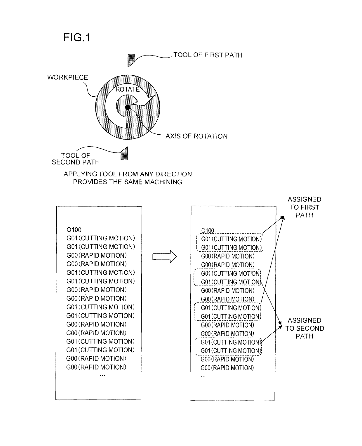
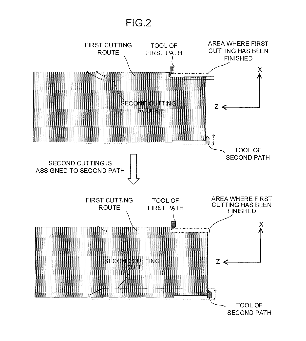
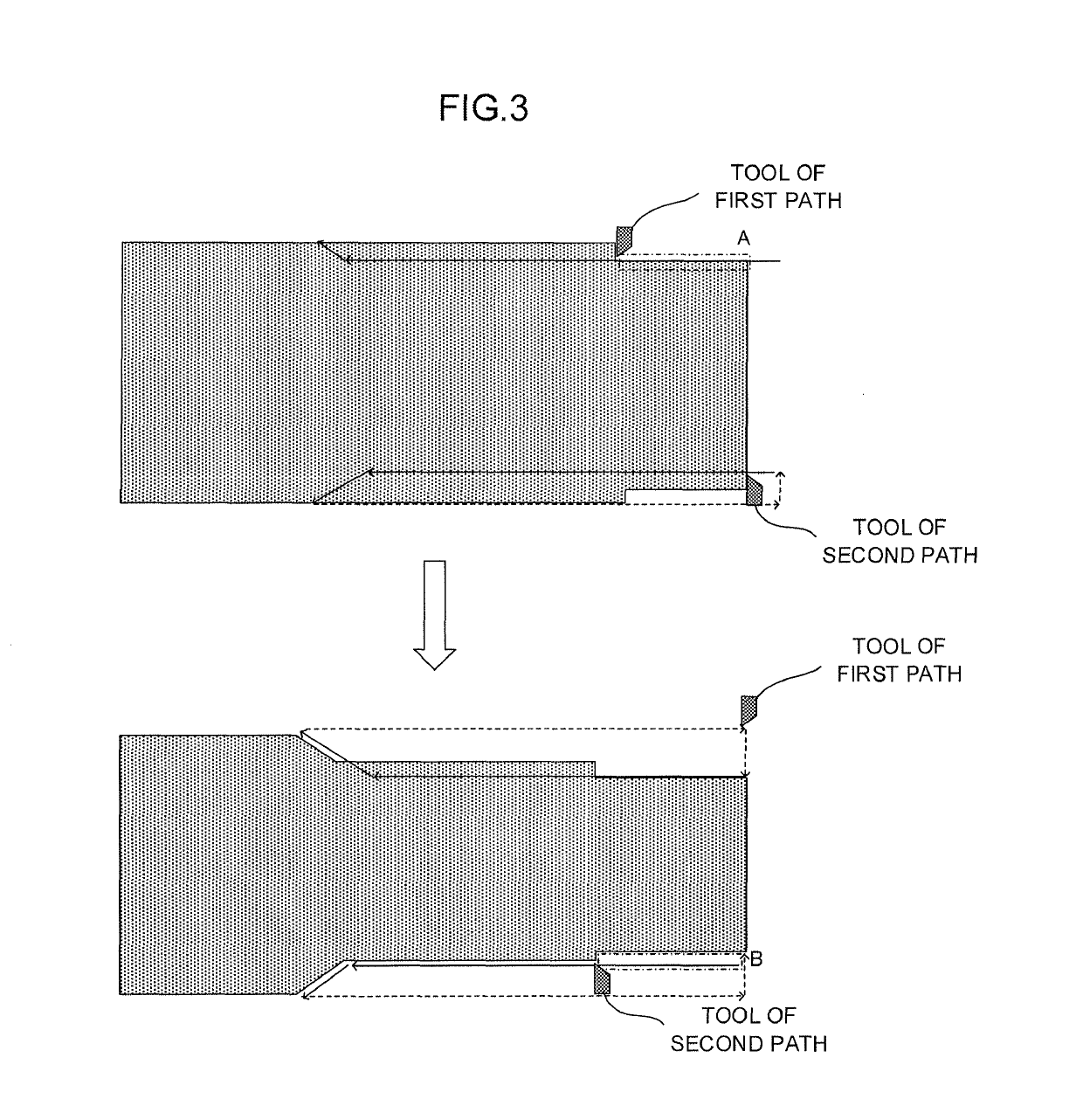
[0052]A numerical controller of the present invention automatically assigns cutting motion commands of a program for a single path to two or more paths and controls the paths based on the assigned commands to perform cutting. As shown in FIG. 1, a cutting program, which mainly includes cutting motions and rapid motions, is separated by rapid motions to create a plurality of sets of cutting motions. Each of the plurality of sets of cutting motions is assigned to one of the paths. The paths are controlled at the same time. Thus, a plurality of cutting motions are executed in an overlapped manner to increase the speed of cutting.

[0053]In the case where control is performed such that two cutting motions of a machining program are allotted to a first path (preceding cutting) and a second path (succeeding c...


PUM


Abstract

A numerical controller of the present invention is a numerical controller for controlling a machine having two or more paths based on a machining program for a single path in which two or more tools are moved in a radial direction of the workpiece and a direction parallel to the axis of rotation to perform cutting, and includes path assignment means for dividing the machining program into cutting motion groups by using rapid motions as delimiters, assigning the cutting motion groups which are divided to the two or more paths, and generating path assignment information in which the cutting motion groups which are assigned are overlapped between a cutting motion group located earlier on the machining program and a cutting motion group located later such that a cutting position by the cutting motion group located later does not overtake a cutting position by the cutting motion group located earlier.

Description

BACKGROUND OF THE INVENTION[0001]1. Field of the Invention[0002]The present invention relates to a numerical controller and a simulator and, more particularly, to a numerical controller which controls axes of two or more paths using a program for a single path, and a simulator thereof.[0003]2. Description of the Related Art[0004]FIG. 23 is a view showing lathe working. In lathe working, a workpiece (object to be machined) attached to a main axis is rotated, and a tool is moved in a radial direction of the workpiece and in a direction parallel to the axis of rotation to perform cutting. The tool is fixed to a support called a tool rest. A machine having a single tool rest is called a single-path (or mono-path) machine, and a machine having two or more tool rests is called a multi-path (or two-or-more-path) machine. In lathe working which does not require main axis positioning, applying the tool to the workpiece toward the axis of rotation of the workpiece from any direction provides ...

Claims


Application Information

Patent Timeline
Patent Type & Authority Patents(United States)
IPC IPC(8): G05B19/19G05B19/4063G05B19/4069
CPCG05B19/19G05B19/4063G05B19/4069G05B2219/49111G05B2219/36071G05B19/18G05B2219/35168
Inventor OKITA, HIROSHI
Owner FANUC LTD
Learn More