Lens barrel and optical apparatus

a technology of optical apparatus and lens barrel, which is applied in the direction of mountings, optics, instruments, etc., can solve the problems of difficult adjustment, difficult to have the necessary strength of the lens barrel, etc., and achieve the effect of reducing the space for arranging movable parts, ensuring sufficient positional stability and shock resistance, and reducing the siz

Active Publication Date: 2019-04-09
SAMSUNG ELECTRONICS CO LTD
View PDF14 Cites 0 Cited by
  • Summary
  • Abstract
  • Description
  • Claims
  • Application Information

AI Technical Summary

Benefits of technology

[0009]According to an objective of exemplary embodiments, there is proided a lens barrel, which has a reduced size embodied by securing sufficient positional stability and shock resistance of parts arranged therein (e.g., movable groups) and reducing spaces for arranging movable parts, and an optical apparatus.

Problems solved by technology

In other words, if there is a cut portion formed by cutting a portion of the outer wall in the lengthwise direction thereof, it may be difficult for a lens barrel to have necessary strength.
However, it might also be difficult to accommodate because of the size reduction of a lens barrel.

Method used


Image

  • Lens barrel and optical apparatus
  • Lens barrel and optical apparatus
  • Lens barrel and optical apparatus

Examples


first embodiment

[0075]The difference between the lens barrel according to the present embodiment and the lens barrel 2 is that, since the movable frame 32 may be a single element, a first assembly unit, that is, assembly grooves 33 arranged at the movable frame 32 are arranged to be assembled to assembly protrusions 34 arranged at the fixed frame 30.

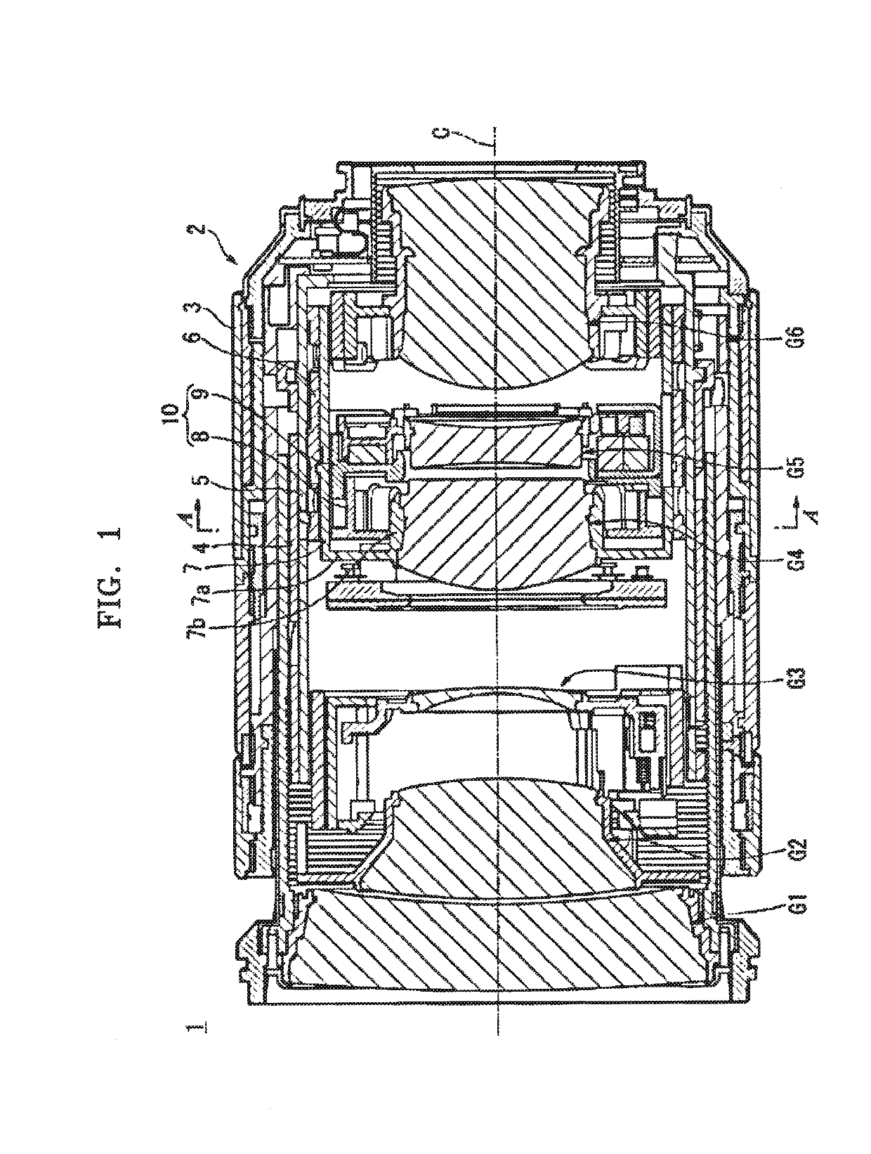
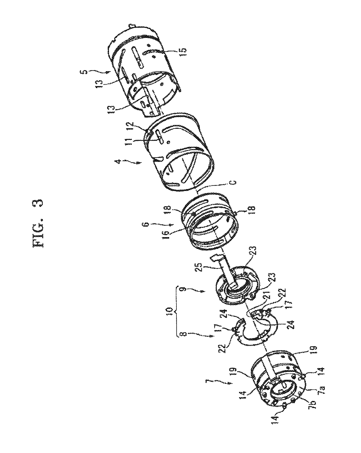
[0076]For example, in the lens barrel according to this exemplary embodiment, the configuration of the movable frame 32 is similar to that of the fourth lens group movable frame 7 shown in FIGS. 1 and 3. In this exemplary embodiment, like the fourth lens group movable frame 7, the movable frame 32 may include a toric portion 32a at a side of the outer wall of the movable frame 32 and include a cylindrical inner barrel 32b at the inner circumferential portion of the toric portion 7a. Furthermore, because a lens group (the lens frame 9) is supported inside the inner barrel 32b, the supported lens group may move straight (forward or backward) as the movab...

third embodiment

[0085]An exchangeable lens according to this exemplary embodiment is identical to the exchangeable lens 1 including the lens barrel 2 except that the exchangeable lens includes the fifth lens group movable frame 40 consisting of a first sub-frame 41, a second sub-frame 42, a third sub-frame 43, and a lens frame 44 instead of the fifth lens group movable frame 10 that consists of the first frame 8 and the lens frame 9 and is arranged in the fourth lens group movable frame 7. Therefore, detailed descriptions of the components of the fifth lens group movable frame 40 will be given below.

[0086]As shown in FIGS. 8 through 10, the fifth lens group movable frame 40 includes the cylindrical first sub-frame 41, the cylindrical second sub-frame 42, the ring-like third sub-frame 43 that is supported by a pair of line shafts 45a and 45b between the first sub-frame 41 and the second sub-frame 42, and the cylindrical lens frame 44 that is arranged at the back of the second sub-frame 42. In addit...


PUM


Abstract

A lens barrel having a reduced size and a related optical apparatus is disclosed. The lens barrel includes a cylindrical fixed frame and a cylindrical movable frame. The cylindrical first frame includes an outer wall extending around the optical axis and a cylindrical second frame is inserted thereto the first frame. The first frame includes a notch having first assembly portions at both side portions. The second frame includes second assembly portions that are assembled to be fixed to the first assembly portions.

Description

CROSS-REFERENCE TO RELATED APPLICATIONS[0001]This application claims the benefit from Japanese Patent Application No. 2015-080223, filed on Apr. 9, 2015, Japanese Patent Application No. 2015-246042, filed on Dec. 17, 2015, in the Japanese Patent Office, and Korean Patent Application No. 10-2016-0027135, filed on Mar. 7, 2016, in the Korean Patent Office, and the disclosures of which are incorporated herein by reference in their entireties.BACKGROUND[0002]1. Field[0003]Apparatuses consistent with exemplary embodiments relate to a lens barrel and an optical apparatus.[0004]2. Description of the Related Art[0005]Recently, as the sizes of imaging apparatuses, such as cameras, reduce, demands for small optical apparatuses are increasing. An example of optical apparatuses, used as a component of a camera, may be a so-called zoom lens by which a user may freely change a focal length. A zoom lens may include therein a mechanism for moving lens groups and a mechanism for supporting and movin...

Claims


Application Information

Patent Timeline
Patent Type & Authority Patents(United States)
IPC IPC(8): G02B27/64G02B7/10
CPCG02B7/102G02B27/646
Inventor SHIMIZU, YOSHIAKI
Owner SAMSUNG ELECTRONICS CO LTD
Why Eureka
Try Eureka