
Miniature sounder

a technology of miniature sounder and electronic terminal, which is applied in the direction of transducer details, electrical transducers, electrical apparatus, etc., can solve the problems of difficult design, limited arrangement of wireless antennas, and relatively complex so as to reduce design difficulty, simplify the assembling process, and effectively simplify the internal structure of electronic terminals

Active Publication Date: 2019-03-26
GOERTEK INC
View PDF11 Cites 0 Cited by
  • Summary
  • Abstract
  • Description
  • Claims
  • Application Information

AI Technical Summary

Benefits of technology

The present invention provides a miniature sounder that has both audio and wireless transceiving functions. This simplifies the inner structure of electronic terminals and facilitates thin and small development of the terminal. The miniature sounder has two electrical connectors that support transmission of both audio and antenna signals. The antenna has an opening close to the pad, which increases the effective length and strength of the signal transmitted and received. The positioning block on the housing helps in identifying the electrical connector connected to the antenna, reducing assembly difficulty and improving the quality of the finished electronic terminal. The technical effects of the invention include simplified structure, reduced design and assembly difficulties, saved internal space, and facilitation of thin and small development of the electronic terminal.

Problems solved by technology

The arrangement of the wireless antenna is greatly limited because the electronic terminal is becoming thinner and smaller.
As a result, the electronic terminal is relatively complex in internal structure, difficult to design and large in occupied space, blocking thin and small development of the electronic terminal.

Method used


Image

  • Miniature sounder
  • Miniature sounder

Examples


Embodiment Construction

[0030]Embodiments of the present invention is further described below with reference to the accompanying drawings and embodiments.

[0031]In this description, the term “inner side” refers to the side close to the center of the miniature sounder; the term “outer side” refers to the side far from the center of the miniature sounder; the orientation “upper” means the vibration system direction, and the orientation “lower” means the magnetic circuit system direction.

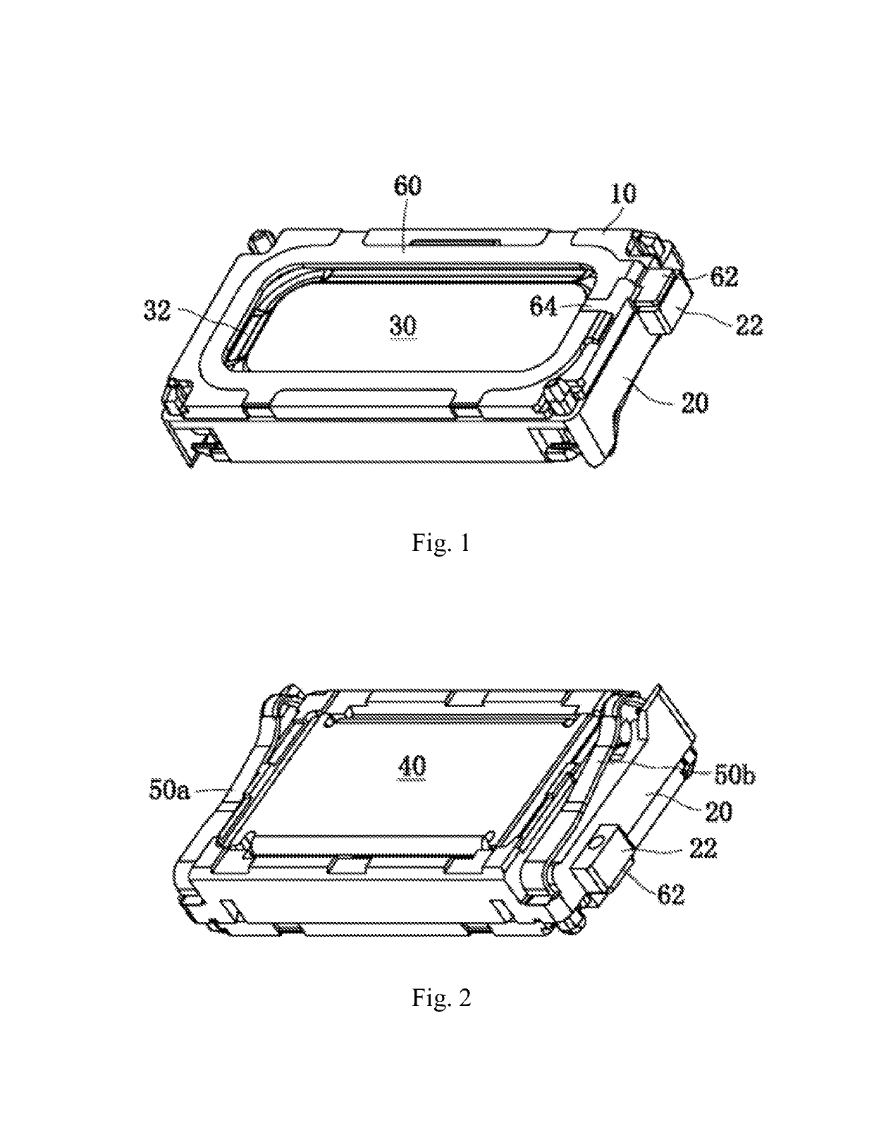
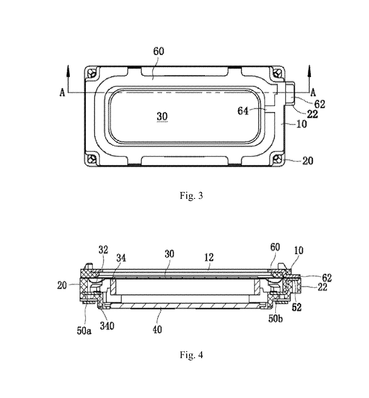
[0032]As shown in FIGS. 1, 2 and 4, a miniature sounder is mounted in an electronic terminal, adopts a rectangular structure, and comprises a housing 20 and a front cover 10 which are combined together. The housing 20 is of a ring structure formed by four side walls and having two open ends; and a vibration system and a magnetic circuit system are accommodated in the space formed by the housing 20 and the front cover 10 in a surrounding manner. The two opposite sides of the end of the housing 20 not combined with the front cov...


PUM


Abstract

A miniature sounder is mounted in an electronic terminal and comprises a front cover and a housing that are combined together. A vibration system and a magnetic circuit system are accommodated in a space formed by the front cover and the housing in a surrounding manner. Two electrical connection members used for being electrically connected to the vibration system and the electronic terminal is disposed on the housing. An antenna of the electronic terminal is fixedly on the front cover, and the antenna is electrically connected to one of the two electrical connection members, and is electrically connected to a circuit of the electronic terminal by means of the electrical connection members. In the miniature sounder in the present invention, a wireless transceiver function is added to an original sounding function of the miniature sounder, the structure of the electronic terminal is effectively simplified, the design difficulty and the assembly difficulty of the electronic terminal are reduced, the internal space of the electronic terminal is saved, which further promoting the electronic terminal to develop towards a light, thin and compact trend.

Description

CROSS-REFERENCE TO RELATED APPLICATIONS[0001]This application is a National Stage of International Application No. PCT / CN2015 / 096957, filed on Dec. 10, 2015, which claims priority to Chinese Patent Application No. 201520669159.2, filed on Aug. 31, 2015, both of which are hereby incorporated by reference in their entireties.BACKGROUND[0002]Technical Field[0003]Embodiments of the present invention relate to the field of electro-acoustic products, and in particular, to a miniature sounder.[0004]Description of Related Art[0005]Embodiments of the present invention relates to the technical field of electroacoustic products, and in particular, to a miniature sounder applied to an electronic terminal with a wireless transceiving function.[0006]As an important acoustic component in an electronic terminal, a miniature sounder for realizing conversion between an electrical signal and a sound signal is an energy conversion apparatus. A conventional miniature sounder generally comprises a housin...

Claims


Application Information

Patent Timeline
Patent Type & Authority Patents(United States)
IPC IPC(8): H04R3/00H04R31/00H04R9/06H04R1/02H04R9/02
CPCH04R9/06H04R9/02H04R31/00H04R31/006H04R2499/11H04R3/00H04R9/025H04R2420/07
Inventor ZHENG, ZEDONGLIU, ZHENHUAZHU, YUEGUANGLIU, HONGTAO
Owner GOERTEK INC
Learn More