
Device and method for measuring plant growth conditions

a technology of growth conditions and devices, applied in watering devices, material impedances, instruments, etc., can solve the problems of limiting the information that can be obtained using such techniques, affecting the quality of plant growth, so as to achieve the effect of simplifying the manufacture of one par

Active Publication Date: 2019-03-19
ROCKWOOL AS
View PDF11 Cites 0 Cited by
  • Summary
  • Abstract
  • Description
  • Claims
  • Application Information

AI Technical Summary

Benefits of technology

[0019]Unlike conventional sensors for use in detecting plant growth conditions, the device of the first aspect obtains multiple measurements of at least one property of the substrate. Two linear arrays of probes are provided at a fixed separation from one another, enabling the two measurements to be obtained at different locations within the substrate. By a ‘linear’ array of the probes it will be understood that the probes in one array are located at approximately the same distance from the probes forming the other array to thereby measure a property at a substrate level. As the relative positions of these locations are fixed (and corresponding to the distance between the two different levels in the substrate), the conditions within the substrate can be modelled from the two measurements in a predetermined manner, enabling a clearer and more accurate understanding of the plant growth conditions within the substrate to be established. Specifically, by taking two measurements at different depths in the substrate for example, an improved calculation of the true plant growth conditions can be achieved, as these conditions vary throughout the substrate, particularly in the vertical direction.
[0026]Preferably, the probes are rotationally asymmetric at a distal end. For example, the probes may be oblique truncated cylinders. By cutting the distal end of generally cylindrical probes through an oblique plane, a relatively sharp distal edge is established thereby assisting in the introduction of the probes into the substrate. The device can therefore be applied to the substrate with relative ease. Moreover, bunching of fibres within the substrates can be avoided in comparison with probes having a blunt end. This is beneficial since such bunching may have an effect on measured properties of the substrate.
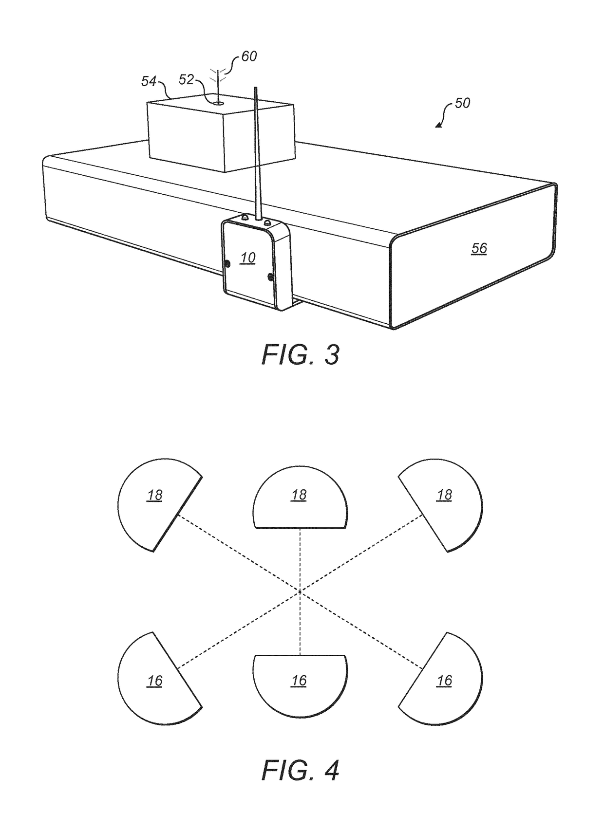
[0029]Preferably, the device further comprises an antenna for transmitting signals to a base station. In this way, measurements and calculated conditions can be retrieved without physical inspection of the device or without the need to a physical connection. This is advantageous in anticipated commercial settings, in which large numbers of substrates are managed within a single area.
[0031]The guide element may be connected to the device by adjustable retaining means. This can allow for adjustment of the relative positions of the guide element and the probes, so that a distance of the probes from an edge of the substrate may be reliably set and adjusted as required, for different sizes of substrate, or for different growth conditions or measurement requirements.
[0033]The adjustable retaining means may comprise an array of main engagement points on one of a main body of the device and the guide element, and a set of corresponding guide element engagement points on the other of the main body and the guide element, for engaging a sub-set of the array of main engaging points. This can enable a simple construction of one part, with a single set of engaging points, while a more complex array of plural sets of engagement points can be provided in the other part of the device. This allows a simpler manufacture of one part, such as the guide element, and can confine the more complex features of the device to a single element—such as the main body of the device.
[0034]The device may further comprise at least one blanking element for engaging main engagement points which are not engaged by the guide element engagement points. This can prevent, water, dirt or dust or other unwanted substances from obstructing the engagement points which are un-used by the mounting of the guide element in a certain position. It can also prevent unwanted substances from entering a main body of the device via holes which may be provided as engagement points for the guide element.

Problems solved by technology

However, if control at this relatively fine level is to be achieved, then measurement of the plant growth conditions is critical.
While these approaches find utility, there are limits on the information that can be obtained using such techniques.
Accordingly, attempts to measure water content and nutrient level from an electrical response can be too limited or variable.
The calculation is further complicated by the properties of the substrate itself.
Nevertheless, water content remains variable throughout the substrate, making a reliable a consistent assessment of overall conditions difficult.

Method used


Image

  • Device and method for measuring plant growth conditions
  • Device and method for measuring plant growth conditions
  • Device and method for measuring plant growth conditions

Examples


Embodiment Construction

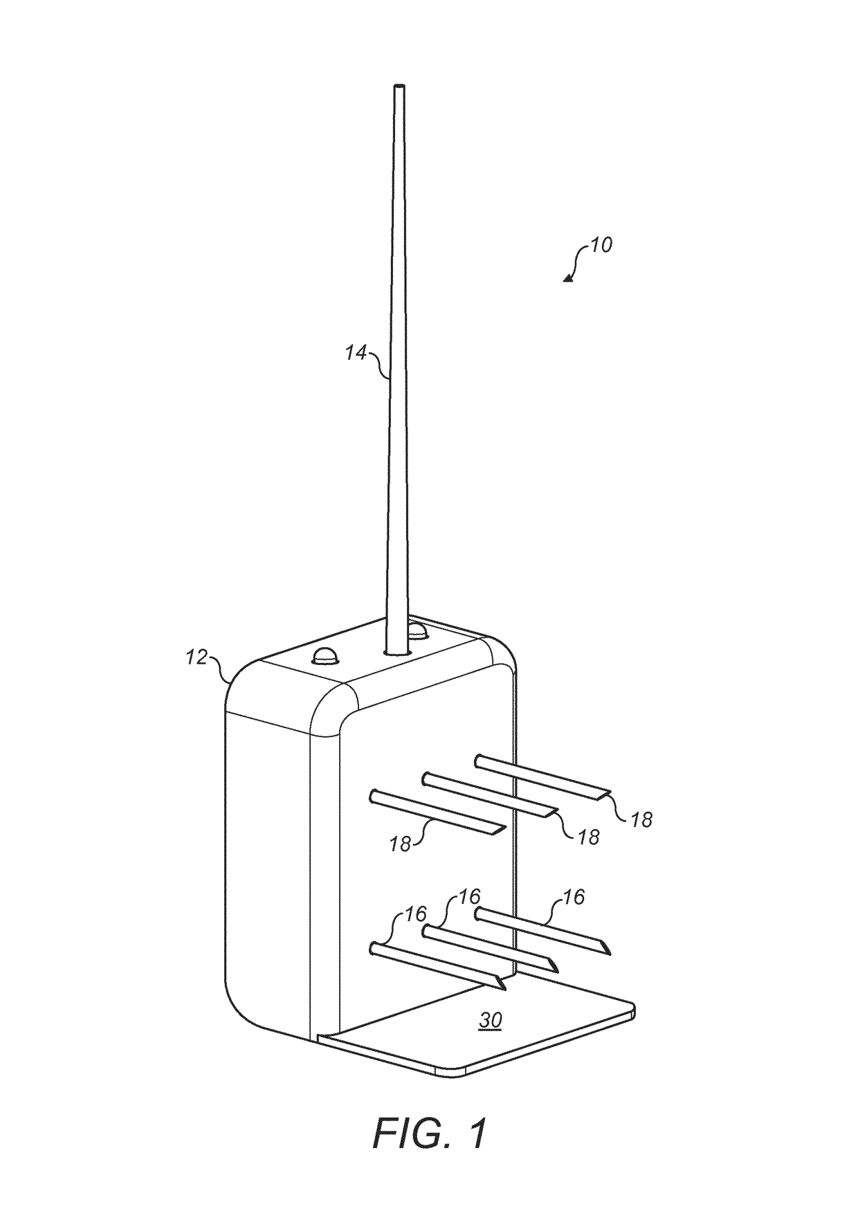
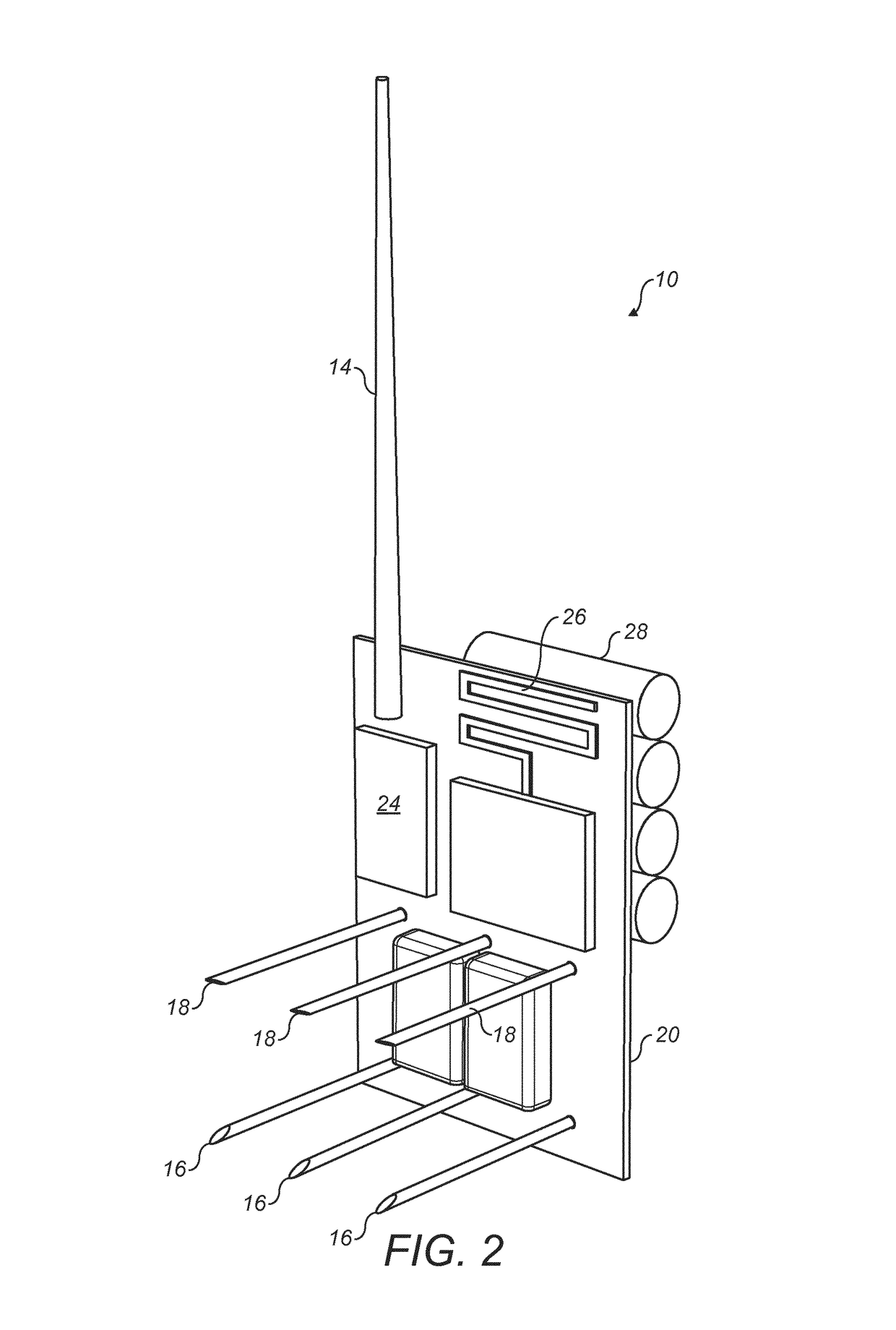
[0058]Referring to FIG. 1, a preferred embodiment of a device 10 for detecting plant growth conditions is shown. The device 10 comprises a body 12, an antenna 14, a first array of probes 16 and a second array of probes 18. Each array of probes 16, 18 are fixed to the body 12 of the device, meaning that the distance between the arrays is itself fixed.

[0059]The device 10 may further comprise additional features not shown in FIG. 1, such as a visible indicator (for example, a light emitting device (LED)) to indicate whether the device 10 is switched on or a user interface to allow the user to control the device 10. In a simple example, the control of the device may be limited to an on / off switch.

[0060]In the preferred embodiment shown in FIG. 1, each array of probes 16, 18 consists of three individual probes. In preferred embodiments, two of these may act as electrodes, with a third acting as a temperature sensor. The electrodes can be used to probe electrical properties of the substra...


PUM

PropertyMeasurementUnit
radiusaaaaaaaaaa
radiusaaaaaaaaaa
frequencyaaaaaaaaaa

Abstract

A device (10) and method are provided for measuring the plant growth conditions within a substrate. A first and a second linear arrays of probes (16, 18) are used, allowing multiple measurements of properties of the substrate. Using multiple measurements at different levels in the substrate and then combining these multiple measurements, allows plant growth conditions to be accurately derived.

Description

FIELD OF THE INVENTION[0001]The present invention relates to the detection of plant growth conditions within plant growth substrates. In particular, but not exclusively, the present invention relates to devices designed for use with artificial plant growth substrates, such as mineral wool substrates.BACKGROUND TO THE INVENTION[0002]In recent years, the management and steering of plant growth has become increasingly specialised and closely managed. Whereas irrigation strategies were once applied field-wide with a general aim merely to compensate for lack of rainwater, plants are increasingly fed water in small groups or even individually with the aim of carefully controlling plant growth conditions.[0003]For example, it is recognised that irrigation strategies can have a qualitative effect on the growth of plants. As is understood in the art, generative growth refers to a type of growth in which the production of flowers / fruit is encouraged, while during vegetative growth the plant a...

Claims


Application Information

Patent Timeline
Patent Type & Authority Patents(United States)
IPC IPC(8): G01N33/00A01G25/16A01G31/02G01N27/22G01N27/04G01N27/02A01G24/18
CPCG01N33/0098A01G25/167A01G31/02G01N27/041G01N27/223G01N27/028Y02P60/216A01G24/18Y02P60/21A01G25/16
Inventor DE GROOT, JACOB FRANK
Owner ROCKWOOL AS
Learn More