
Display panel and display apparatus using the same

a technology which is applied in the field of display panel and display device, can solve the problems of image blurryness, poor performance, and image sensor limitation by fixed focal length rang

Active Publication Date: 2019-03-05
HKC CORP LTD +1
View PDF22 Cites 4 Cited by
  • Summary
  • Abstract
  • Description
  • Claims
  • Application Information

AI Technical Summary

Benefits of technology

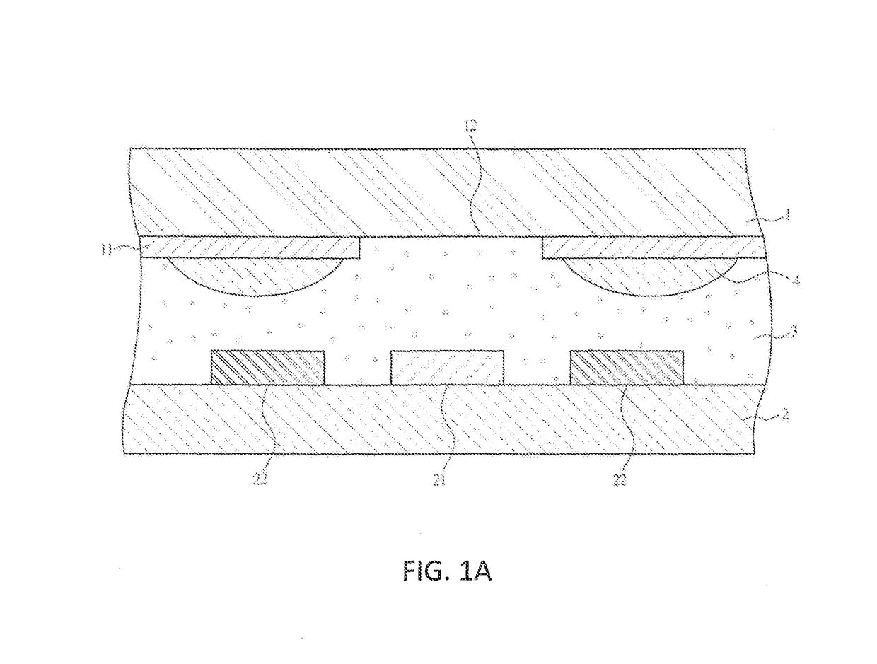
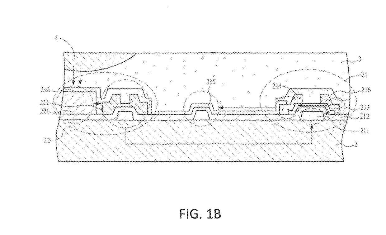
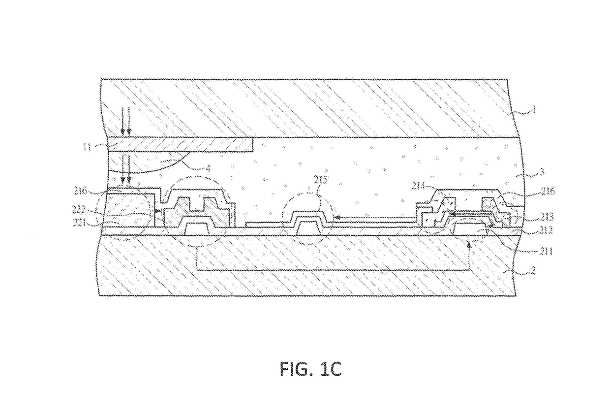
The present invention provides a display panel and display apparatus that are free of the influence of depth of field but have an adjustable focal length. This improves the performance and usability of the display panel and allows it to meet the requirements of being light, thin, and short. The invention is achieved by combining an adjustable zoom image sensing module and a lens array on a thin film transistor liquid crystal display panel. This allows for an adjustable zoom effect and overcomes the current problem without being limited by depth of field. The lens array is manufactured using a thin film transistor substrate, which is small and not impacted by the size of the system. The invention also allows for image recognition and vein sensing.

Problems solved by technology

If away from a focus point of the lens within the fixed distance range, an image will be getting blurry.
However, an image sensor is limited by its fixed focal length range.
Therefore, an imaging effect will be determined by the fixed depth of field and has accordingly a poor performance.
Furthermore, a traditional glass lens or plastic lens has only one fixed focal length, and cannot provide an adjustable zoom function.
However, the volume of the voice coil motor itself is very large, resulting in a problem of traditional autofocus modules being correspondingly large.
Therefore, an application of this kind of traditional lens group is very difficult and limited.

Method used


Image

  • Display panel and display apparatus using the same
  • Display panel and display apparatus using the same
  • Display panel and display apparatus using the same

Examples


Embodiment Construction

[0039]The drawings as referred to throughout the description of the present invention are examples for implementing the objects of the present invention. The orientation words or terms used in the description of the present invention, such as “above”, “under”, “forward”, “backward”, “left”, “right”, “inner”, “outer”, “side”, etc. are examples in the drawings for illustrative purpose only, or just show the interrelations between the components, but not to be construed as limitations to the scope of the present invention.

[0040]The drawings and the description of the present invention are deemed to be examples but not limitations essentially. In the drawings, components or elements having similar or same structure are marked with the same numbers. In addition, sizes and thicknesses of every component or element are just examples, but not drawn according to actual scale and not read as limitations to the scope of the present invention.

[0041]In drawings of the present invention, sizes an...


PUM

PropertyMeasurementUnit
energy band gapaaaaaaaaaa
focal lengthaaaaaaaaaa
areaaaaaaaaaaa

Abstract

The present invention provides a display panel and a display apparatus using the same. The display panel comprises: a first substrate; a second substrate; a liquid crystal layer disposed between the first substrate and the second substrate; an image sensing module disposed on one side of the second substrate facing the first substrate; a lens array disposed on one side of the first substrate facing the second substrate and on a position corresponding to the image sensing module; and an active switch array disposed on the side of the second substrate facing the first substrate, wherein the image sensing module is configured to receive the focused image light.

Description

BACKGROUND OF THE INVENTIONField of Invention[0001]The present invention generally relates to a display panel and a display apparatus using the same, and especially to a display panel and a display apparatus, and the display panel and the display apparatus thereof are free of influence of a depth of field and have an adjustable focal length function.Description of Related Art[0002]A depth of field refers to a relative range for clear imaging around the focus of an image sensing device. In optics, especially in photograph or video field, a depth of field is related to a special distance range for clear imaging (a distance between the nearest and farthest clear image appeared). A general lens can focus light on a fixed distance range for clear imaging, wherein a clear image can be formed. If away from a focus point of the lens within the fixed distance range, an image will be getting blurry. Within the fixed distance range, the blurry degree of the image is invisible to the naked huma...

Claims


Application Information

Patent Timeline
Patent Type & Authority Patents(United States)
IPC IPC(8): H04N5/222G06F3/041H04N5/232H04N5/225G06F3/042G02F1/1335G02F1/1368G02B1/04G02F1/133
CPCH04N5/232125G02B1/041G02F1/1368H04N5/2257G02F1/133509G02F1/133526G02F1/13318G02F2203/11H04N23/57H04N23/959H04N25/76
Inventor CHO, EN-TSUNGYANG, FENGYUN
Owner HKC CORP LTD
Learn More