
System for the automatic deployment of traffic control signs during a power outage

a technology of automatic deployment and traffic control, applied in the direction of traffic control of road vehicles, traffic signals, controlling traffic signals, etc., can solve the problems of increasing the rate of serious accidents and injuries, the response is not always possible, and the traffic can become quite hectic and unsafe, so as to eliminate the confusion of drivers and enhance the public safety

Inactive Publication Date: 2019-02-26
SNYDER SAFETY TECH LLC
View PDF5 Cites 0 Cited by
  • Summary
  • Abstract
  • Description
  • Claims
  • Application Information

AI Technical Summary

Benefits of technology

The present invention is a new system that automatically deploys traffic control signs during power outages to enhance public safety. It can be placed at multiple roadway intersections and structures, providing an alternative means to deploy safety and other information. Additionally, the system eliminates driver confusion when deployed, making it easier for them to see and respond to the signs. The technical effects of this invention include improving safety and efficiency on roadways, as well as simplifying the process of deploying traffic control signs during power outages.

Problems solved by technology

Traffic can become quite hectic and unsafe when power outages occur due to storms, inclement weather, malfunctions and the like.
When for example thunderstorms cause traffic lights to become inoperable, the rates of serious accidents and injuries increase significantly.
However, their response is not always possible and certainly never instantaneous upon the loss of power.
However, these devices run out of power, stop working, require recharging and are relatively expensive.

Method used


Image

  • System for the automatic deployment of traffic control signs during a power outage
  • System for the automatic deployment of traffic control signs during a power outage
  • System for the automatic deployment of traffic control signs during a power outage

Examples


Embodiment Construction

[0022]As described above, the present invention provides a new and useful system for the automatic deployment of traffic control signs during a power outage which enhances public safety, automatically deploys in the event of power outage, can be placed in a plurality of roadway intersections and structures, provides an alternative means to deploy safety and other information, and eliminates driver confusion when deployed. This system is believed to be useful in a variety of environments and by agencies such as municipal, state and federal departments of transportation. The following description and accompanying drawings disclose at least one version of the device.

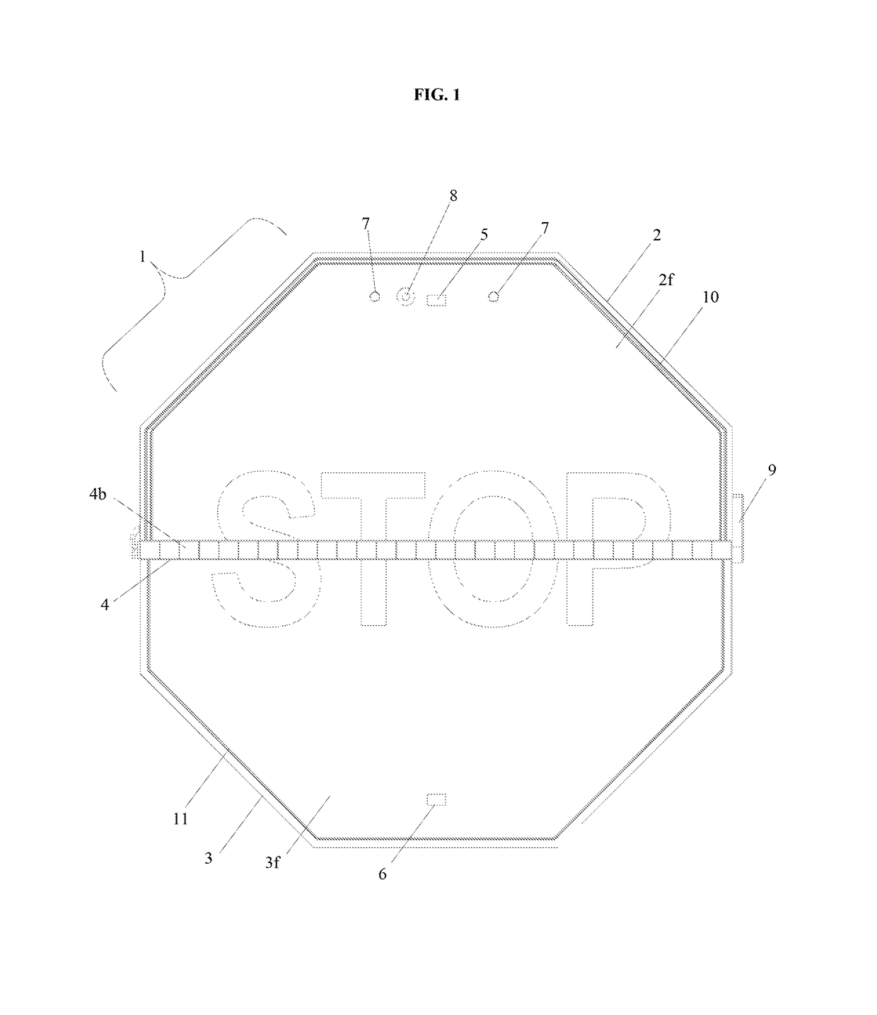
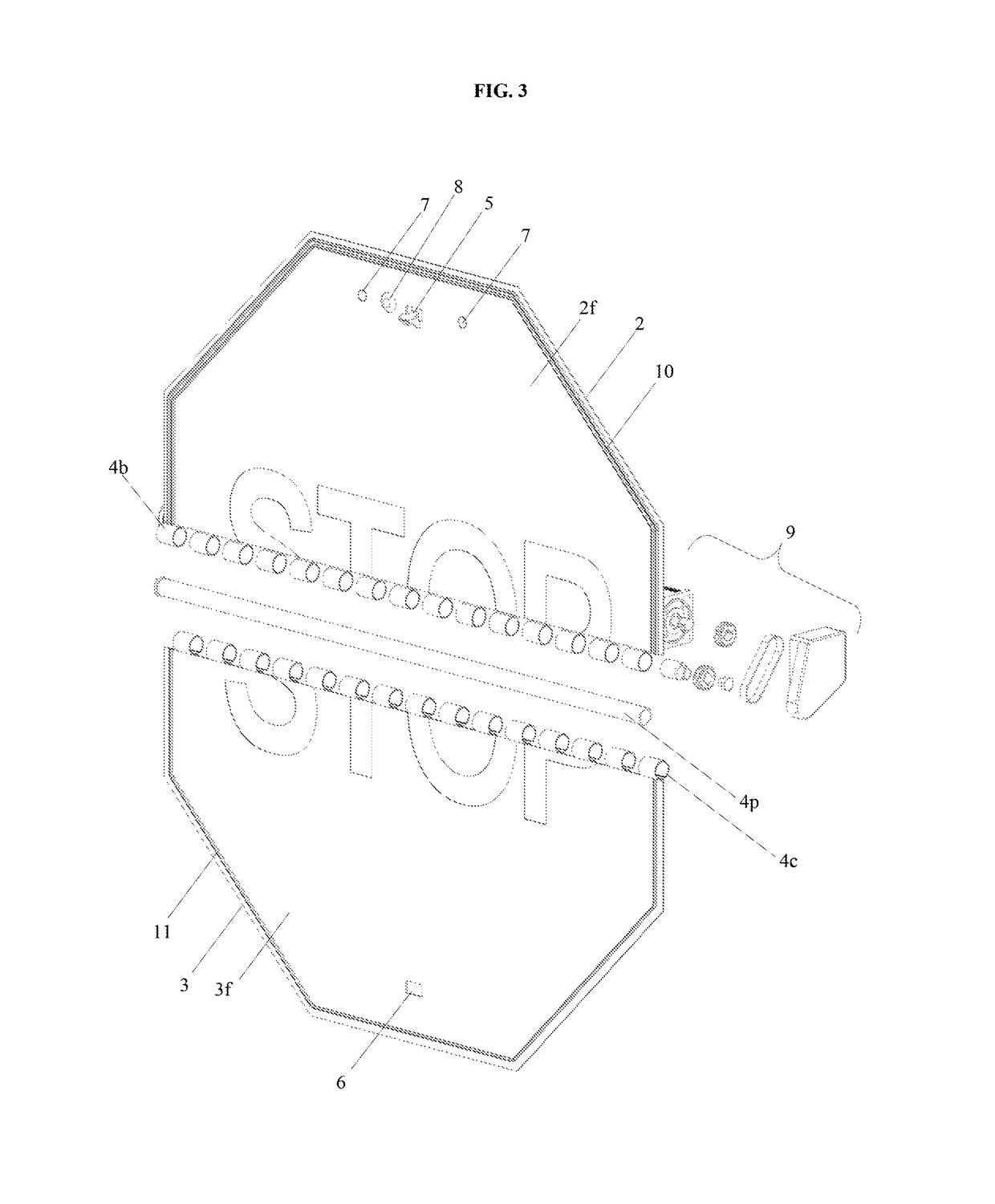
[0023]Referring now to FIG. 1 to FIG. 8 and FIG. 10 there is shown a system for the automatic deployment of traffic control signs during a power outage which comprises a traffic sign 1 that is bisected horizontally and has a top half portion 2 and a bottom half portion 3 wherein the top half portion 2 has a top half portion...


PUM


Abstract

A system for the automatic deployment of traffic control signs during a power outage which enhances public safety, automatically deploys in the event of power outage, can be placed in a plurality of roadway intersections and structures, provides an alternative means to deploy safety and other information, and eliminates driver confusion when deployed. The system essentially comprises a traffic control sign that is bisected and having a top half portion and a bottom half portion connected by a hinge means, an electromagnet attached to the approximate center of the top half portion front surface, an armature plate attached to the bottom half portion front surface, an attaching means attached to the top half portion back surface for affixing the system to a structure in an environment, and at least one power cable extending from the electromagnet and connecting to a powering means in the environment. This system is believed to be useful in a variety of environments and by agencies such as municipal, state and federal departments of transportation.

Description

TECHNICAL FIELD[0001]This invention relates generally to signs. More specifically this invention relates to traffic control signs. More specifically this invention relates to automated traffic control signs.BACKGROUND OF THE INVENTION[0002]Traffic can become quite hectic and unsafe when power outages occur due to storms, inclement weather, malfunctions and the like. When for example thunderstorms cause traffic lights to become inoperable, the rates of serious accidents and injuries increase significantly. In the current art and in order to reduce accidents, intersections that become inoperable are maintained by a traffic controller or police officers. However, their response is not always possible and certainly never instantaneous upon the loss of power. Therefore, there is a need for a system that can be implemented concomitantly with existing traffic lights which automatically deploy and display safety information in the event of a power outage.[0003]In the current art, there exis...

Claims


Application Information

Patent Timeline
Patent Type & Authority Patents(United States)
IPC IPC(8): G08G1/07G08B29/18
CPCG08G1/07G08B29/181G08G1/095
Inventor SNYDER, JEFFREY
Owner SNYDER SAFETY TECH LLC
Learn More