Advanced lensless light-field imaging systems and methods for enabling a wide range of entirely new applications

a technology of light-field imaging and advanced lensless technology, applied in the field of computation imaging and light-field sensors, can solve the problem that not all such advantages can be achieved

Inactive Publication Date: 2019-02-26
NRI R&D PATENT LICENSING LLC
View PDF34 Cites 3 Cited by
  • Summary
  • Abstract
  • Description
  • Claims
  • Application Information

AI Technical Summary

Problems solved by technology

Not all such advantages can be achieved in accordance with any one particular embodiment.

Method used


Image

  • Advanced lensless light-field imaging systems and methods for enabling a wide range of entirely new applications
  • Advanced lensless light-field imaging systems and methods for enabling a wide range of entirely new applications
  • Advanced lensless light-field imaging systems and methods for enabling a wide range of entirely new applications

Examples


case b

uous Spatially-Varying Separation Distances —Non-Parallel Planes:

[0399]Relaxing the constraints in Case A, the above-described planes of (a) the objects or situations producing contributions to the light-field and (b) the image sensor are not parallel but rather oriented at some non-parallel and non-perpendicular dihedral angle. The resulting light-field has separation mixed distances. The discussion and capabilities of this development explicitly include cases with zero separation distance between at least a subset (even a 1-dimensional edge or even a single point) of a planar array of light-providing “light-source” pixels and a subset (even a 1-dimensional edge or even a single point) of at least a planar array of “light-sensing” pixels.

[0400]As an illustration of Case B, FIGS. 25a and 25b depict a pair of illustrative 3-dimensional views of an example variation of the arrangement depicted in FIG. 24 wherein a planar array of (emitted and / or reflected) light source elements and a ...

example c

s Spatially-Varying Separation Distances—Curved Surfaces:

[0403]Relaxing the constraints in Case A in yet another way, one or both of (a) the objects or situations producing contributions to the light-field and / or (b) the image sensor reside on smoothly-curved non-planar surface. The resulting light-field has separation mixed distances and in some cases possible occultation depending on variations in curvature. The discussion and capabilities of this development explicitly include cases with zero separation distance between at least a subset (even a 1-dimensional edge or even a single point) of a planar array of light-providing “light-source” pixels and a subset (even a 1-dimensional edge or even a single point) of at least a planar array of “light-sensing” pixels.

[0404]As an illustration of Case C, FIGS. 27a and 27b depict a pair of illustrative 3-dimensional views of an example of a non-planar curved surface and a planar surface with a spatially-quantized light-field representation...


PUM


Abstract

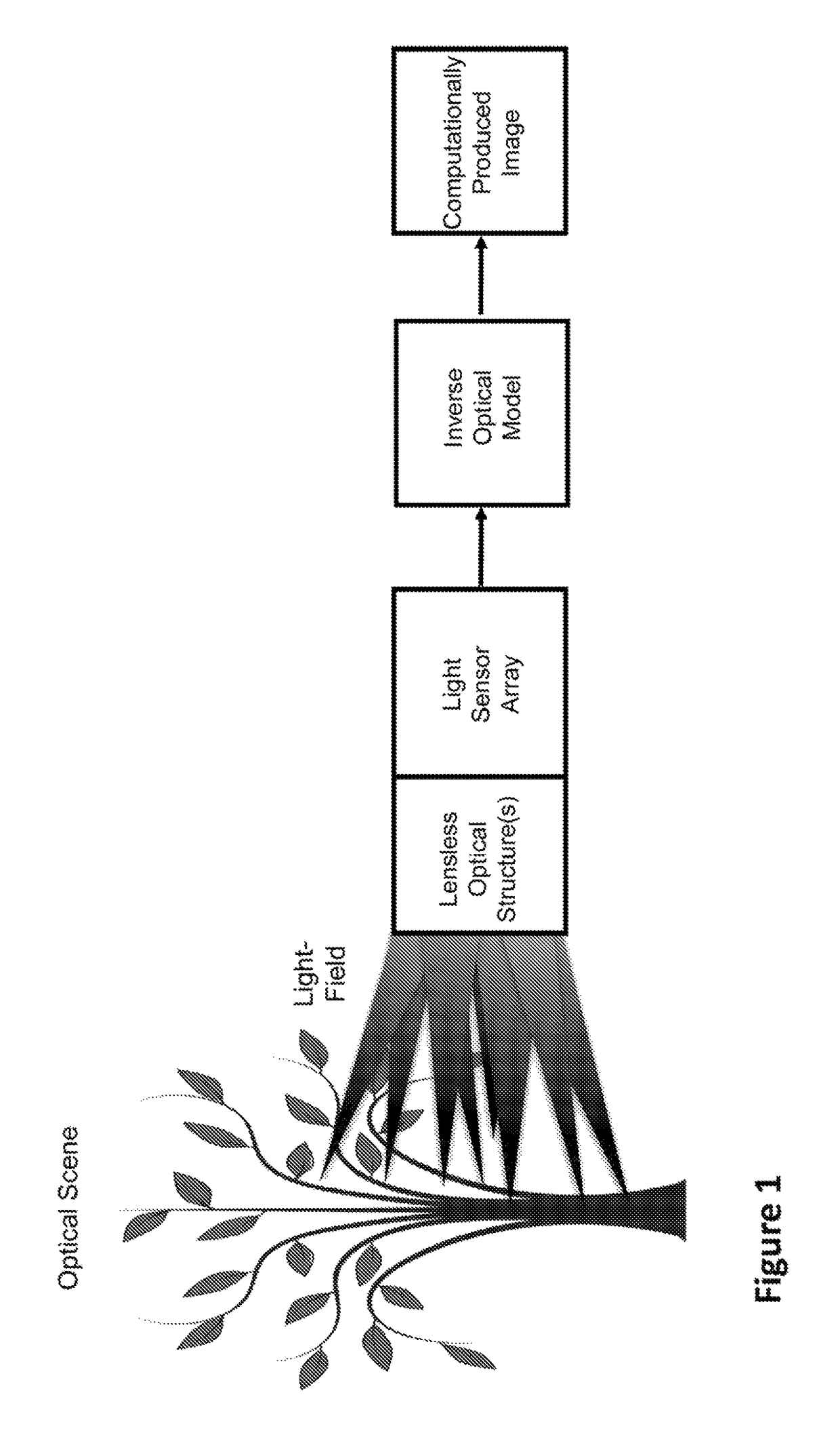
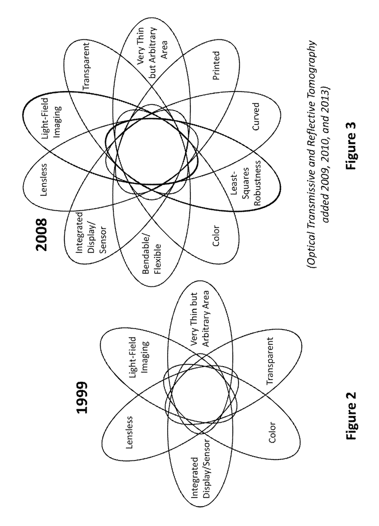
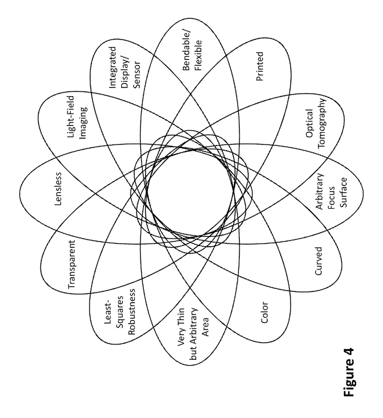
Continuing a sequence of lensless light-field imaging camera patents beginning 1999, the present invention adds light-use efficiency, predictive-model design, distance-parameterized interpolation, computational efficiency, arbitrary shaped surface-of-focus, angular diversity / redundancy, distributed image sensing, plasmon surface propagation, and other fundamentally enabling features. Embodiments can be fabricated entirely by printing, transparent / semi-transparent, layered, of arbitrary size / curvature, flexible / bendable, emit light, focus and self-illuminate at zero-separation distance between (planar or curved) sensing and observed surfaces, robust against damage / occulation, implement color sensing without use of filters or diffraction, overlay on provided surfaces, provided color and enhanced multi-wavelength color sensing, wavelength-selective imaging of near-infrared / near-ultraviolet, and comprise many other fundamentally enabling features. Embodiments can be thinner, larger / smaller, more light-use efficient, and higher-performance than recently-popularized coded aperture imaging cameras. Vast ranges of diverse previously-impossible applications are enabled: credit-card cameras / phones, in-body monitoring of healing / disease, advanced biomarker analysis systems, perfect eye-contact video conferencing, seeing fabrics / skin / housings, and manufacturing-monitoring, wear-monitoring, and machine vision capabilities.

Description

CROSS REFERENCE TO RELATED APPLICATIONS[0001]This application claims the benefit of U.S. Provisional Application No. 62 / 360,472, filed Jul. 11, 2016, and U.S. Provisional Application No. 62 / 528,384, filed Jul. 3, 2017, the disclosures of which are incorporated herein in their entireties by reference.COPYRIGHT & TRADEMARK NOTICES[0002]A portion of the disclosure of this patent document may contain material, which is subject to copyright protection. Certain marks referenced herein may be common law or registered trademarks of the applicant, the assignee or third parties affiliated or unaffiliated with the applicant or the assignee. Use of these marks is for providing an enabling disclosure by way of example and shall not be construed to exclusively limit the scope of the disclosed subject matter to material associated with such marks.BACKGROUND OF THE INVENTIONField of the Invention[0003]The invention pertains to computational imaging and light-field sensors, and more specifically to ...

Claims


Application Information

Patent Timeline
Patent Type & Authority Patents(United States)
IPC IPC(8): G06T7/557H04N5/3745H04N5/378H01L27/30H04N5/225H01L27/28H04N9/04
CPCG06T7/557H01L27/28H01L27/288H01L27/30H01L27/307H04N5/22541H04N5/378H04N5/3745H04N9/045H04N5/225G06T2207/10052G06T2207/10024H04N23/957H04N23/00H04N23/10H10K39/32H04N25/75H04N25/77H10K19/00H10K39/00H10K65/00
Inventor LUDWIG, LESTER F.
Owner NRI R&D PATENT LICENSING LLC
Why Eureka
Try Eureka