
Tool-less wedge-type anti-rattle mounting system for a vehicle-mounted equipment carrier

a technology of vehicle-mounted equipment and mounting system, which is applied in vehicle components, transportation and packaging, supplementary fittings, etc., can solve the problems of bicycles being subjected to unnecessary and potentially damaging vibration and rattling, requiring tools, and significant and noticeable wobble at the upper end of the carrier frame, so as to prevent the rattle of the coupling member and eliminate the effect of substantially all wobble and shaking of the rack

Active Publication Date: 2019-02-26
SARIS EQUIP LLC
View PDF81 Cites 4 Cited by
  • Summary
  • Abstract
  • Description
  • Claims
  • Application Information

AI Technical Summary

Benefits of technology

This patent is about a hitch mounting system for bicyzip racks that reduces the shaking and wobbling of the rack during transport. The system includes a coupling member that goes through the hitch receiver and a brace member that is outside the hitch receiver. A wedge member is moved by an actuator to push the coupling member against the walls of the hitch receiver, which prevents rattling and shaking. This system is easy to install and remove without using tools and makes for a smoother ride for the bicycle.

Problems solved by technology

A problem with hitch rack designs of this type is that the coupling bar or tube does fit closely inside the passage of the hitch receiver, and slight movements or rattling of the coupling bar or tube result in significant and noticeable wobble at the upper end of the carrier frame which supports the bicycles.
As a result, the bicycles are subjected to unnecessary and potentially damaging vibration and rattling.
While designs of this type function to eliminate rattle between the coupling bar and the hitch receiver, they are disadvantageous in their requirement for a tool that must be used to install and remove the rack.
In use, the tool can be misplaced or lost, which can cause a frustrating delay when mounting and / or removing the rack.

Method used


Image

  • Tool-less wedge-type anti-rattle mounting system for a vehicle-mounted equipment carrier
  • Tool-less wedge-type anti-rattle mounting system for a vehicle-mounted equipment carrier
  • Tool-less wedge-type anti-rattle mounting system for a vehicle-mounted equipment carrier

Examples


Embodiment Construction

[0019]The various features and advantageous details of the subject matter disclosed herein are explained more fully with reference to the non-limiting embodiments described in detail in the following description.

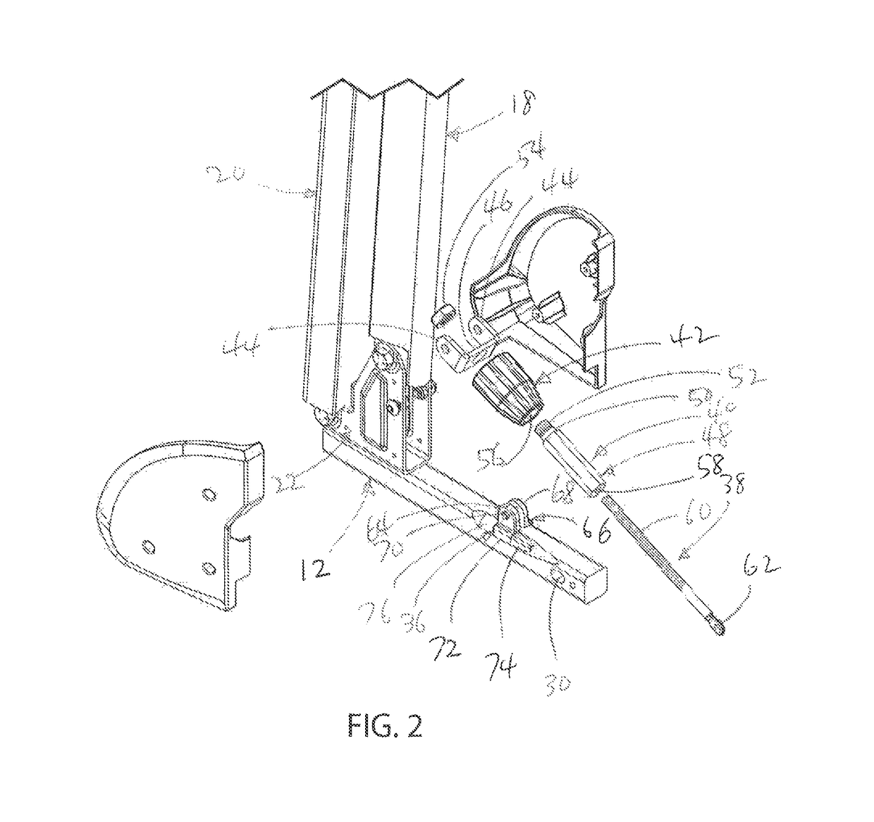
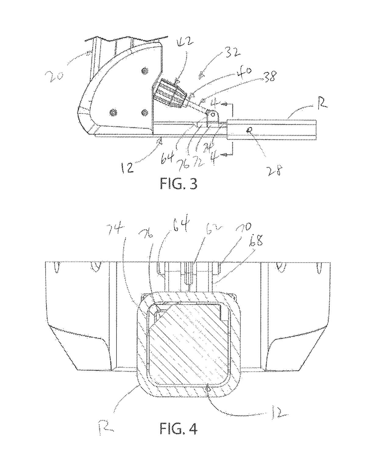
[0020]FIG. 1 illustrates an equipment carrier, generally designated at 10, which is configured for mounting to the rear of a vehicle. Equipment carrier 10 is shown as a bicycle rack or carrier, although it is understood that the present invention may be employed with any type of vehicle-mounted equipment carrier or rack. Generally, equipment carrier 10 includes a mounting member 12, a mast shown generally at 14, and an equipment support arrangement shown generally at 16. In the illustrated embodiment, the mast 14 includes a front mast member 18 and a rear mast member 20, which are pivotably mounted at their lower ends to a lower mounting bracket 22. The equipment support arrangement 16 includes a pair of spaced apart equipment-supporting arms 24, 26, which as noted above are...


PUM


Abstract

A hitch-type equipment carrier for mounting to a vehicle includes a coupling member, a brace member fixed to the coupling member, and a wedge member that is movable relative to the coupling member. A manually operable actuator is positioned between the brace member and the wedge member. When the coupling member is positioned within the hitch receiver passage, operation of the actuator moves the wedge member in a first direction toward the open end of the hitch receiver passage. The wedge member moves outwardly upon advancement through the open end of the hitch receiver passage. Such transverse movement of the wedge member brings the wedge member into contact with one or more walls of the hitch receiver, which forces the coupling member against one or more of almost walls of the hitch receiver for preventing rattle of the coupling member within the passage of the hitch receiver.

Description

CROSS-REFERENCE TO RELATED APPLICATION[0001]This patent application claims the benefit of U.S. provisional patent application Ser. No. 62 / 344,521 filed Jun. 2, 2016, the entire contents of which are hereby expressly incorporated by reference.BACKGROUND AND SUMMARY[0002]This invention relates to vehicle-mounted equipment carriers, such as, but not limited to, carriers for transporting bicycles or other recreational equipment on a vehicle, and more particularly to a wedge-type anti-rattle mounting system for a hitch-mounted equipment carrier.[0003]Many vehicle-mounted equipment carriers or racks, such as bicycle racks, are adapted for mounting to an existing hitch receiver on the back of an automobile or truck. A hitch receiver typically includes a square tube, welded to the frame of the vehicle under the rear bumper, with a passage having an open end for receiving a mating coupling on a trailer. The square tube typically has a pair of, or a series of pairs of, aligned holes on opposi...

Claims


Application Information

Patent Timeline
Patent Type & Authority Patents(United States)
IPC IPC(8): B60R9/06B60R9/10
CPCB60R9/06B60R9/10
Inventor BASS, BENJAMIN RAYMONDWEBER, RYAN
Owner SARIS EQUIP LLC
Learn More