
Modular computer and thermal management

a modular computer and thermal management technology, applied in flow control, process and machine control, instruments, etc., can solve the problems of difficult to squeeze a proper thermal module into the limited space, bulky heat dissipation blocks cannot fit in this thickness, and large thermal modules are required. , to achieve the effect of facilitating air flow, enhancing cooling heat dissipation, and selecting thermal design power

Active Publication Date: 2019-01-22
ICE COMP
View PDF32 Cites 0 Cited by
  • Summary
  • Abstract
  • Description
  • Claims
  • Application Information

AI Technical Summary

Benefits of technology

The present invention provides a hybrid circuit with a high-power and low-power microprocessor that allows users to adjust the thermal design power (TDP) as needed. This results in optimal cooling for the computer core. A separate fan is used to cool the computer core without taking space in the enclosure. Different fan sizes allow for different air volumes and flows, while the heat sink at the end or edge of the computer core takes advantage of the natural air flow to enhance cooling. The position of the heat sink also increases its radiation for communication.

Problems solved by technology

In addition, the size of a typical ultra-computing device (i.e., roughly, the size of a smartphone) makes it difficult to squeeze a proper thermal module into the limited space.
However, to transfer heat away from a higher power microprocessor, a much larger and more complete thermal module is required.
A bulky heat dissipation block does not fit in this thickness.
In addition, it is impossible to put a conventional cooling fan within the confines of the smartphone-size computer.
It is a challenge to computer supplies to find a design that cools down a smartphone size computer in which a high-power microprocessor is used.
However, these new “mini” products do not generate enough airflow to cool a high-power microprocessor in an effective manner.

Method used


Image

  • Modular computer and thermal management
  • Modular computer and thermal management
  • Modular computer and thermal management

Examples


Embodiment Construction

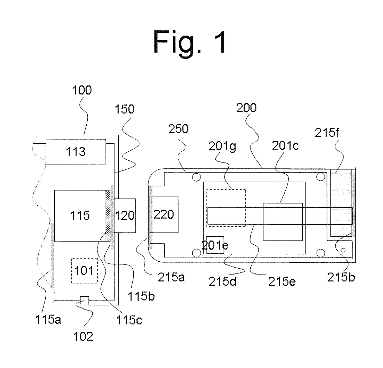
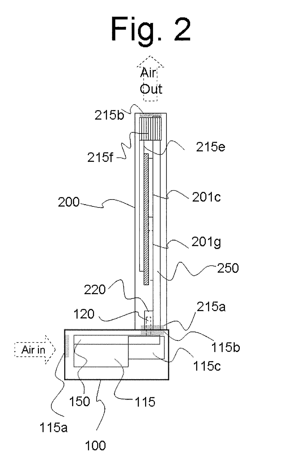
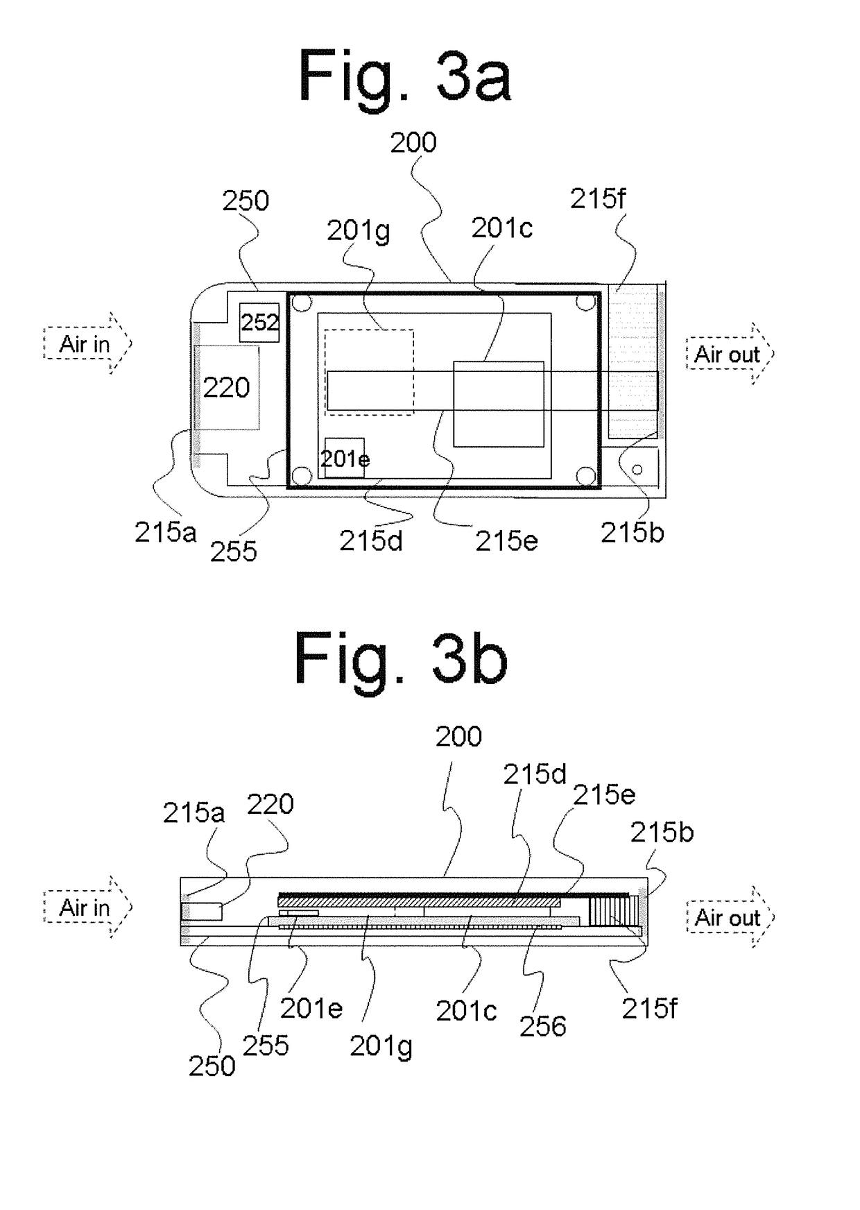
[0025]FIG. 1 is a top view of computer core 200 and a partial view of connected computing device 100. As shown in FIG. 1, computer core 200 is smartphone size and is designed to connect to computing device 100. On base board 250, computer core 200 includes central processing unit (CPU) 201c, graphical processing unit (GPU) 201g, embedded controller 201e, and other computing components. In some embodiments, computer core 200 and computing device 100 are connected through base connector 220 and carrier connector 120 in any manner (e.g., horizontally, vertically, or with a rotation mechanism for an angle less than 270 degree). To simplify this detailed description, a component on computing device 100 is described as “carrier”, while a component on computer core 200 is described as “base”. The pins of these connectors are mapped functionally (e.g., USB pins, A / V pins, power pins, and data pins) to allow proper signals to flow between the computer core 200 and computing device 100. Compu...


PUM


Abstract

An enclosure design facilitates heat dissipation from a space-limited computer core device. An external computer platform is provided to connect the computer core device, the external computer platform including a fan that provides an air flow to the connected computer core device. The computer core device and the computing platform may be tightly connected by connectors located on their respective enclosure walls. Both the computer core device and the external computing platform are provided air inlets and outlets on their respective enclosures. When connected, an air inlet of the computer core device faces an air outlet of the external computing platform such that a single cooling air flow flows through the external computing platform and the computer core device. The external computing platform may include a built-in fan to blow air into or draw air from the matching air inlets and outlets.

Description

CROSS REFERENCE TO RELATED APPLICATIONS[0001]The present application is related to and claims priority of U.S. provisional patent application (“Provisional application”), Ser. No. 61 / 776,682, entitled “Modular Computer and Thermal Management”, filed on Mar. 11, 2013. The disclosure of the Provisional application is hereby incorporated by reference in its entirety.BACKGROUND OF THE INVENTION[0002]1. Field of the Invention[0003]The present invention relates to applications of modular computer cores. More particularly, the present invention relates to the use of a hybrid circuit including a high-power processor and a low-power processor to provide a selectable “thermal design power” (TDP) in a thermal module together with an air-flow design.[0004]2. Discussion of the Related Art[0005]In recent years, small and thin computing devices are highly favored. Some examples of small and thin computing devices include the iPad and the iPhone from Apple Computer, Inc., the “ultrabooks” notebook ...

Claims


Application Information

Patent Timeline
Patent Type & Authority Patents(United States)
IPC IPC(8): G05D7/06G06F1/20G06F1/32
CPCG05D7/0676G06F1/20G06F1/3293Y02D10/122G06F2200/1635Y02D10/00
Inventor CHENG, SHANG-CHEWU, WEI-HANLIN, CHIA-MING
Owner ICE COMP
Learn More