Spectroscopic measurement apparatus, driving circuit, and spectroscopic measurement method

a technology of spectroscopic measurement and driving circuit, applied in the direction of optical radiation measurement, instruments, spectrometry/spectrophotometry/monochromators, etc., can solve the problems of long measurement time, steep change of distance between reflection-films, and non-uniform measurement wavelength intervals

Active Publication Date: 2019-01-08
SEIKO EPSON CORP
View PDF14 Cites 0 Cited by
  • Summary
  • Abstract
  • Description
  • Claims
  • Application Information

AI Technical Summary

Benefits of technology

[0006]An advantage of some aspects of the invention is to provide a spectroscopic measurement apparatus capable of obtaining the results of measurement with a constant measurement wavelength interval, a driving circuit, and a spectroscopic measurement method.
[0008]In this application example, the electrostatic actuator is driven by the driving control section in such a way that the distance between the first reflection film and the second reflection film changes at a uniform velocity. In this case, the wavelength of light outputted from the wavelength variable interference filter changes linearly in relation to elapsed time. Therefore, by performing spectroscopic measurement of detecting the output light in a constant cycle, it is possible to obtain the results of spectroscopic measurement with a constant measurement wavelength interval (with suppression of non-uniformity in measurement wavelength interval). Moreover, when scan processing for spectroscopic measurement is performed in a constant cycle while changing the distance between the first reflection film and the second reflection film (between-reflection-films distance) from a predetermined maximum value to a predetermined minimum value, it is possible to obtain the measurement results with suppression of non-uniformity in measurement wavelength interval just by performing scan processing once. It is not necessary to perform scan processing plural times and, therefore, it is possible to reduce the time taken for measurement.
[0009]Preferably, in the spectroscopic measurement apparatus according to the above application example, the driving control section should include a voltage output section that outputs a pulse voltage of a predetermined cycle and a low pass filter that outputs a driving voltage that corresponds to the pulse voltage for driving the electrostatic actuator. In general, in an electrostatic actuator, electrostatic attraction that is proportional to the square of a voltage applied between a pair of electrodes and is inversely proportional to the square of the distance between the electrodes acts. Therefore, when a pulse voltage that has a rectangular waveform for minimizing the between-reflection-films distance is inputted into the electrostatic actuator directly, the between-reflection-films distance changes steeply in an accelerated manner and, therefore, it is difficult to obtain the results of spectroscopic measurement with a constant measurement wavelength interval. In contrast, in this application example, a pulse voltage of a predetermined cycle outputted from the voltage output section is inputted into the low pass filter, and a driving voltage outputted from the low pass filter is inputted into the electrostatic actuator. That is, when a pulse voltage (rectangular waveform) is inputted into the low pass filter, the inputted pulse voltage is converted into a driving voltage that has a first-order-lag waveform corresponding to the time constant τ, and the driving signal is inputted into the electrostatic actuator. That is, in the initial state in which no voltage is applied to the electrostatic actuator and the value of the between-reflection-films distance is great, a voltage that is comparatively great in the inclination of a voltage value in relation to elapsed time (change percentage) is inputted. As the value of the between-reflection-films distance decreases, a voltage of a gentler slope is inputted into the electrostatic actuator. In this application example, the low pass filter is configured to make the distance change velocity of the between-reflection-films distance uniform or substantially uniform when the above-described driving voltage having the first-order-lag waveform is inputted and, therefore, with a simple structure, it is possible to change the between-reflection-films distance at a uniform velocity or at a substantially uniform velocity, thereby obtaining the results of spectroscopic measurement with a constant measurement wavelength interval speedily.
[0011]Preferably, the spectroscopic measurement apparatus according to the above application example should further comprise: a distance detection section that detects the distance between the first reflection film and the second reflection film, and the time constant changing section should change the time constant in such a way that a change in the distance detected by the distance detection section is uniform in velocity. In this application example, the between-reflection-films distance is detected by the distance detection section. The time constant changing section changes, therefore, the time constant on the basis of the detected distance. That is, it is possible to set, with high precision, a time constant that ensures that the between-reflection-films distance changes at a uniform velocity.
[0013]Preferably, the spectroscopic measurement apparatus according to the above application example should further comprise: a light receiving unit that receives light outputted from the wavelength variable interference filter, wherein a signal from the light receiving unit should be acquired in a constant cycle. In this application example, the signal outputted from the light receiving unit is acquired in a constant cycle. In this application example, as described above, the between-reflection-films distance changes at a uniform velocity or at a substantially uniform velocity. Therefore, by performing signal acquisition from the light receiving unit in a constant cycle, it is possible to acquire the signal for light of measurement wavelength with a constant measurement wavelength interval. Therefore, it is possible to obtain the results of spectroscopic measurement that are free from non-uniformity in measurement wavelength interval.
[0014]Preferably, in the spectroscopic measurement apparatus according to the above application example, the driving control section should include a voltage output section that outputs a pulse voltage of a predetermined cycle and a low pass filter that outputs a driving voltage that corresponds to the pulse voltage for driving the electrostatic actuator, a time constant of the low pass filter being variable, and the spectroscopic measurement apparatus according to the above application example should further comprise: a distance detection section that detects the distance between the first reflection film and the second reflection film; and a time constant changing section that changes the time constant in such a way that an amount of a change in the distance detected by the distance detection section is constant, wherein acquisition timing of the signal from the light receiving unit and detection timing of the distance by the distance detection section should be different from each other. In a case where the signal from the distance detection section (distance detection signal) and the signal from the light receiving unit (received signal) are acquired at the same time, it is necessary to process the two signals at the same time. In some cases, this makes the response time of each circuit and the time taken for AD conversion long, resulting in a wide measurement wavelength interval. In contrast, in this application example, the acquisition timing of the distance detection signal and the acquisition timing of the received signal are different from each other. Since it is unnecessary to process the two signals at the same time, it is possible to make the response time of each circuit and the time taken for AD conversion short, thereby reducing the cycle of acquisition of the received light signal and the detection signal. This makes it possible to reduce the measurement wavelength interval and obtain the results of spectroscopic measurement with high resolution.

Problems solved by technology

In this case, the gap change velocity is not constant when the light outputted from the wavelength variable interference filter is detected by the detection unit and, therefore, non-uniformity in measurement wavelength interval appears when the signal from the detection unit is acquired at a constant time interval.
In such a case, it is necessary to perform scan plural times and, therefore, it takes long to complete the measurement.
Therefore, when a pulse voltage that has a rectangular waveform for minimizing the between-reflection-films distance is inputted into the electrostatic actuator directly, the between-reflection-films distance changes steeply in an accelerated manner and, therefore, it is difficult to obtain the results of spectroscopic measurement with a constant measurement wavelength interval.
However, in some cases, the distance change velocity of the between-reflection-films distance could change due to, for example, a change in the installation environment or driving environment of the wavelength variable interference filter.
In some cases, this makes the response time of each circuit and the time taken for AD conversion long, resulting in a wide measurement wavelength interval.

Method used


Image

  • Spectroscopic measurement apparatus, driving circuit, and spectroscopic measurement method
  • Spectroscopic measurement apparatus, driving circuit, and spectroscopic measurement method
  • Spectroscopic measurement apparatus, driving circuit, and spectroscopic measurement method

Examples


first embodiment

[0028]A spectroscopic measurement apparatus according to a first embodiment of the invention will now be explained.

Configuration of Spectroscopic Measurement Apparatus

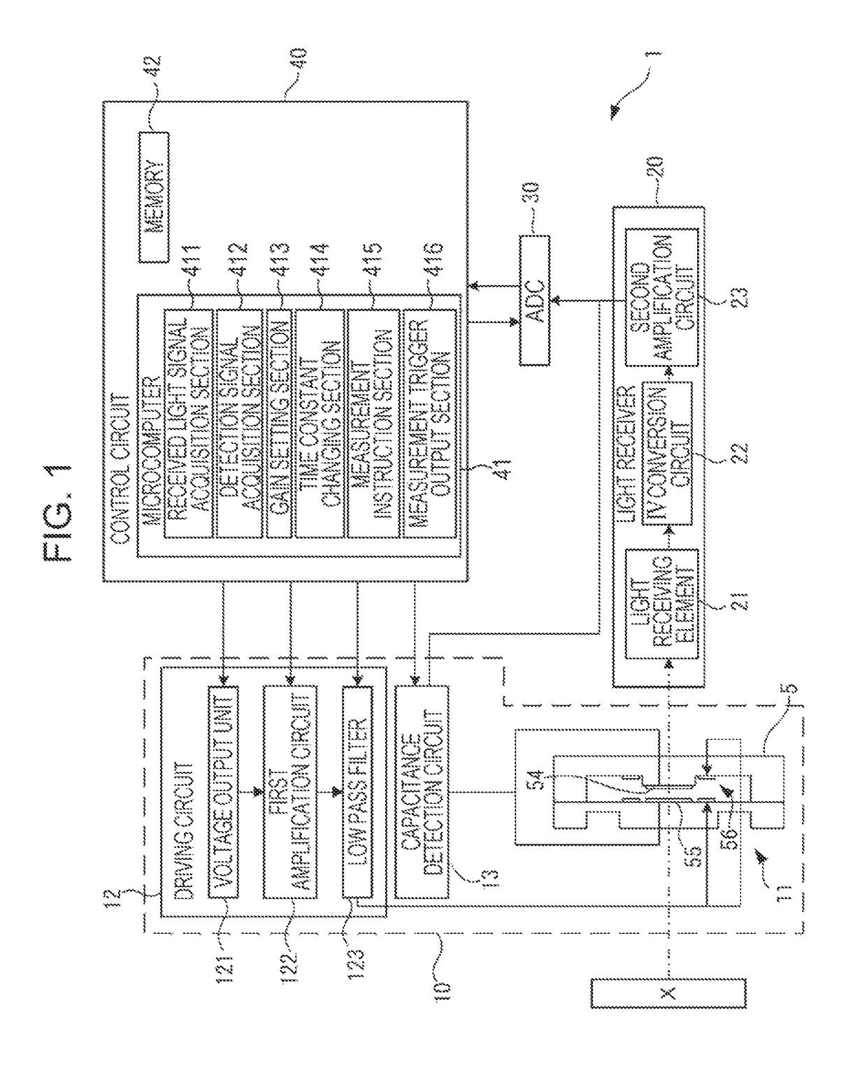
[0029]FIG. 1 is a block diagram that illustrates the schematic configuration of a spectroscopic measurement apparatus according to an exemplary embodiment of the invention. A spectroscopic measurement apparatus 1 is an apparatus that analyzes the optical intensity of each wavelength of incident light coming in from a measurement target X and measures its spectrum. As illustrated in FIG. 1, the spectroscopic measurement apparatus 1 includes an optical module 10, a light receiver 20, an ADC 30, and a control circuit 40. The optical module 10 includes an optical filter device 11, a driving circuit 12, and a capacitance detection circuit 13. The optical module 10 may further include a light source unit that applies illuminating light to the measurement target X.

Structure of Optical Filter Device

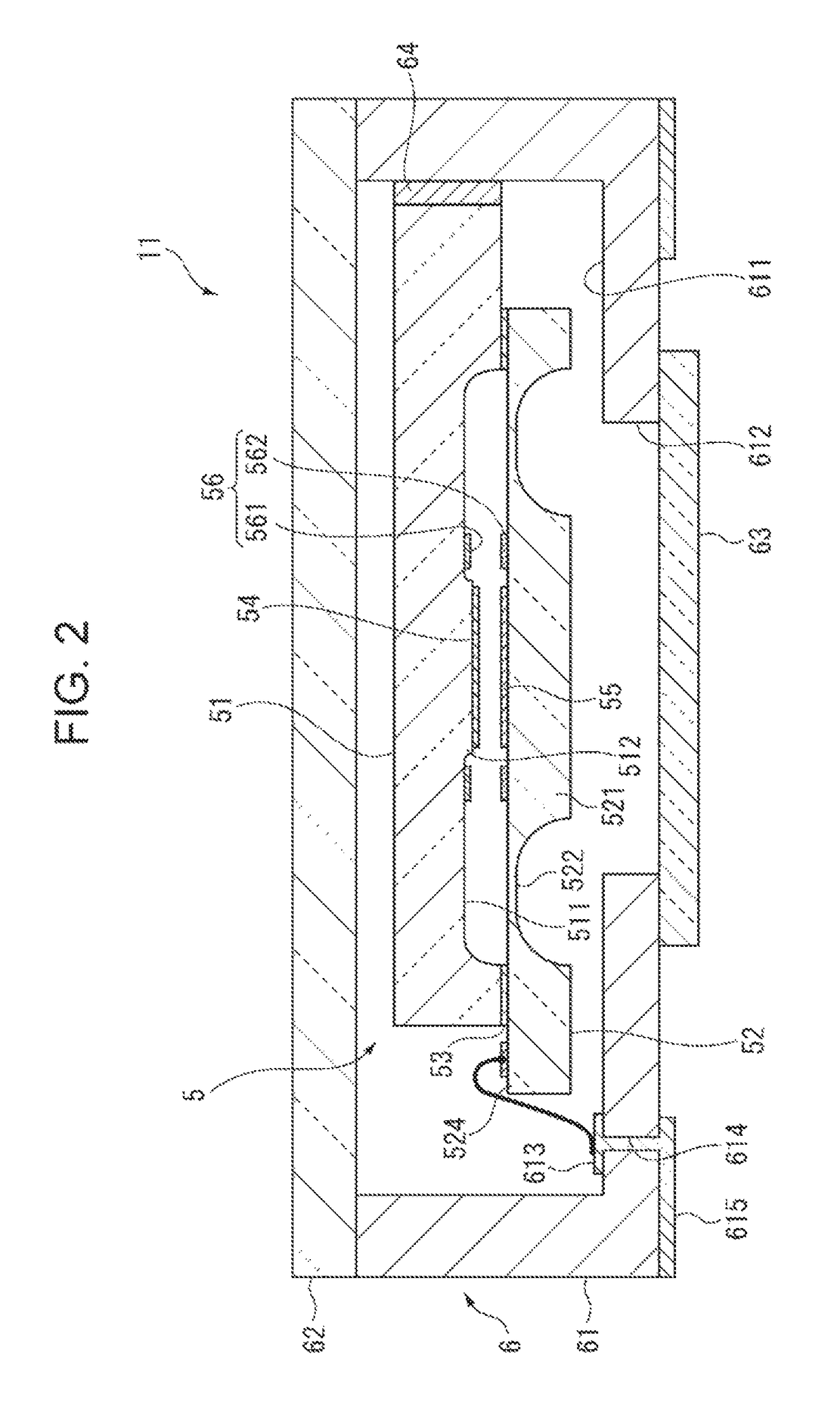
[0030]FIG. 2 is a sectional ...

second embodiment

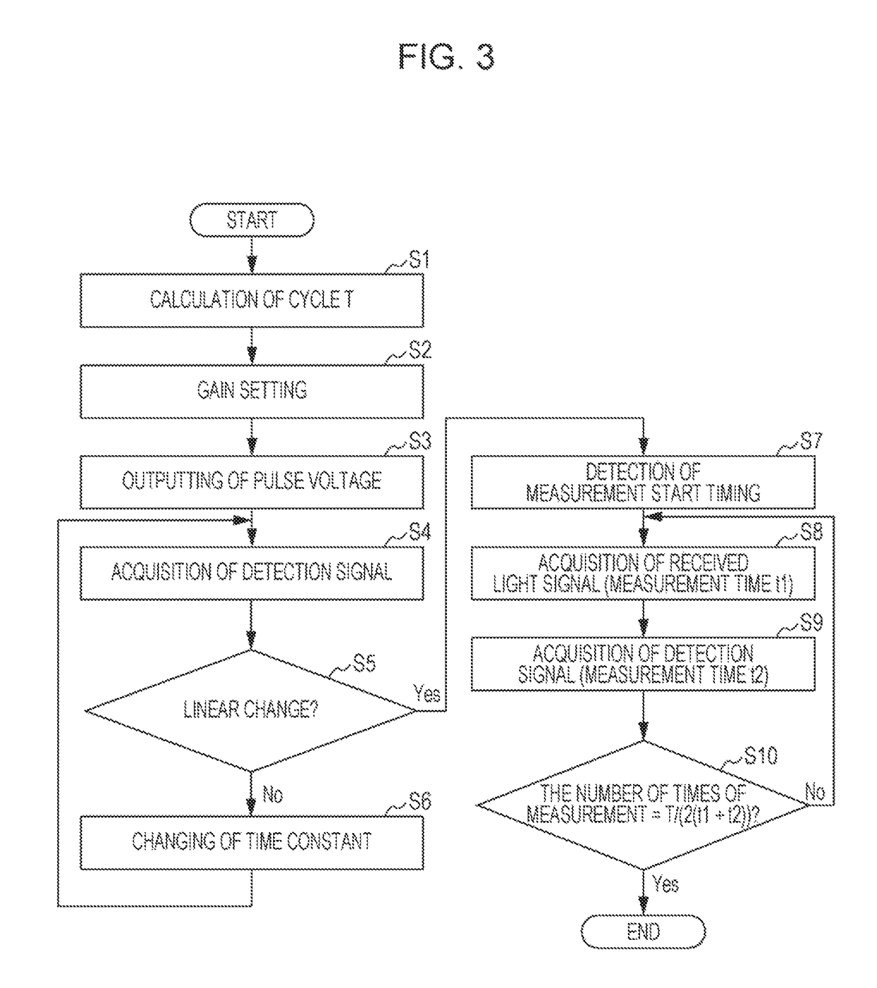
[0076]Next, a second embodiment of the present invention will now be explained. In the example of the first embodiment described above, a received light signal and a detection signal are acquired at the same time in the sampling cycle. The second embodiment is different from the first embodiment in that the acquisition timing of a received light signal and the acquisition timing of a detection signal are different from each other. A spectroscopic measurement apparatus 1 according to the second embodiment has the same structure as that of the first embodiment illustrated in FIGS. 1 and 2. Therefore, a detailed explanation of each component in the structure is omitted here. FIG. 7 is a flowchart that illustrates a spectroscopic measurement method in the spectroscopic measurement apparatus 1 of the second embodiment.

[0077]In the second embodiment, processing in steps S1 to S6 is performed similarly to that of the first embodiment as illustrated in FIG. 7. In the present embodiment, the...

third embodiment

[0081]Next, a third embodiment of the present invention will now be explained. In the third embodiment, with reference to the accompanying drawings, an example of an electronic device in which the spectroscopic measurement apparatus 1 described above in the first and second embodiments is built will now be explained.

Schematic Structure of Printer

[0082]FIG. 8 is a schematic perspective view of the appearance of a printer 100 according to a third embodiment. FIG. 9 is a block diagram that illustrates the schematic structure of the printer 100 according to the third embodiment. As illustrated in FIG. 8, the printer 100 includes a feeder unit 110, a transportation unit 120, a carriage 130, a carriage movement unit 140, and a control unit 150 (refer to FIG. 9). On the basis of print data inputted from, for example, a personal computer, the printer 100 controls each of the units 110, 120, and 140 and the carriage 130 to print an image on a medium M. The printer 100 of the present embodime...


PUM


Abstract

A spectroscopic measurement apparatus includes a wavelength variable interference filter and a driving circuit. The wavelength variable interference filter includes a fixed reflection film, a movable reflection film that faces the fixed reflection film, and an electrostatic actuator that changes a distance between the fixed reflection film and the movable reflection film. The driving circuit drives the electrostatic actuator in such a way that the distance between the fixed reflection film and the movable reflection film changes at a uniform velocity.

Description

BACKGROUND[0001]1. Technical Field[0002]The present invention relates to a spectroscopic measurement apparatus, a driving circuit, and a spectroscopic measurement method, etc.[0003]2. Related Art[0004]A spectroscopic measurement apparatus that includes a wavelength variable interference filter is known. For example, a spectroscopic measurement apparatus disclosed in JP-A-2013-092474 is provided with a wavelength variable interference filter that includes a pair of reflection films facing each other, wherein the distance between the pair of reflection films is changed in accordance with measurement wavelength. In the spectroscopic measurement apparatus disclosed in JP-A-2013-092474, an electrostatic actuator that changes a distance between the pair of reflection films is provided, and an analog voltage that changes in a continuous manner is applied to the electrostatic actuator. The voltage applied to the electrostatic actuator is monitored. When the monitored voltage becomes equal t...

Claims


Application Information

Patent Timeline
Patent Type & Authority Patents(United States)
IPC IPC(8): G01J3/26G01J3/02
CPCG01J3/0275G01J3/26G01J3/027
Inventor KURI, RYOHEI
Owner SEIKO EPSON CORP
Why Eureka
Try Eureka