
Liquid dispenser with manifold mount for modular independently-actuated pipette channels

a technology of independent actuators and liquid dispensers, applied in the direction of transportation and packaging, instruments, laboratory glassware, etc., can solve the problem of laborious sample preparation in par

Active Publication Date: 2019-01-01
BECTON DICKINSON & CO
View PDF27 Cites 3 Cited by
  • Summary
  • Abstract
  • Description
  • Claims
  • Application Information

AI Technical Summary

Benefits of technology

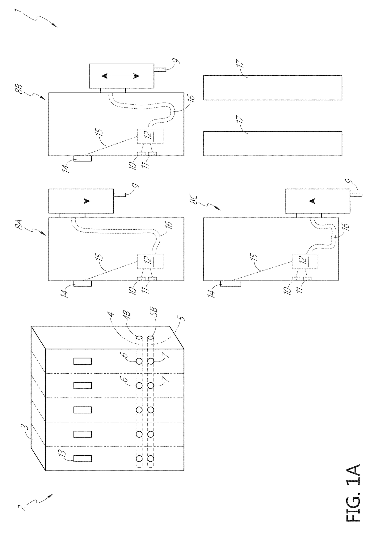
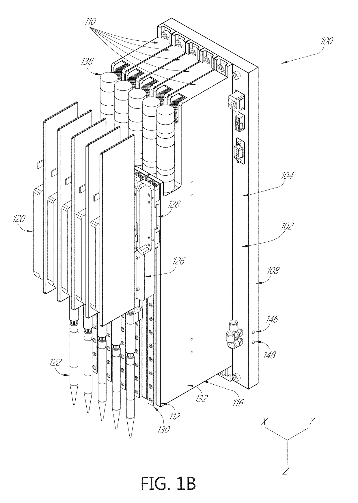
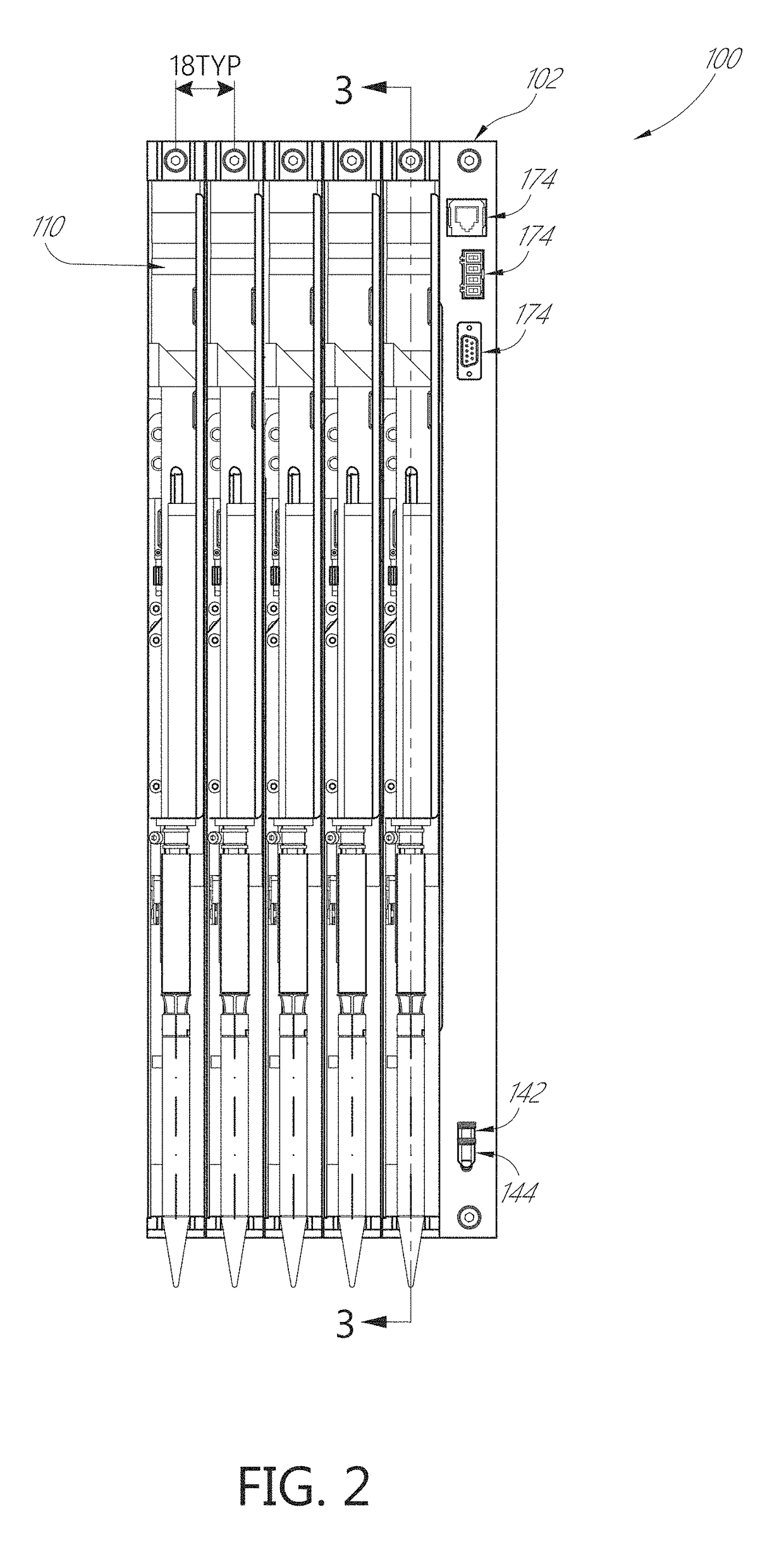
The patent describes a liquid dispenser that includes a manifold with a pressure channel and a vacuum channel, each with a cross-section that can be adjusted independently. The manifold has a valve that can selectively divert gas under pressure or vacuum to a dispense head. The dispenser also includes one or more pipette channels that can be selectively coupled to the manifold. Each pipette channel has its own pressure and vacuum port, and a valve that can control the distribution of gas to the dispense head. The liquid dispenser can be powered independently and has separate electrical connections for each channel. The patent also describes a design with separate pressure and vacuum channels, as well as a design with different calibration settings for each channel. The liquid dispenser can also have different dispense heads for different channels.

Problems solved by technology

Sample preparation is labor intensive in part because of the number of liquids, such as reagents, that are required, and the need for multiple liquid transfer (e.g., pipetting) operations.

Method used


Image

  • Liquid dispenser with manifold mount for modular independently-actuated pipette channels
  • Liquid dispenser with manifold mount for modular independently-actuated pipette channels
  • Liquid dispenser with manifold mount for modular independently-actuated pipette channels

Examples


Embodiment Construction

[0026]Any feature or combination of features described herein are included within the scope of the present disclosure provided that the features included in any such combination are not mutually inconsistent as will be apparent from the context, this description, and the knowledge of one skilled in the art. In addition, any feature or combination of features may be specifically excluded from any embodiment of the present disclosure. For purposes of summarizing the present disclosure, certain aspects, advantages, and novel features of the present disclosure are described herein. Of course, it is to be understood that not necessarily all such aspects, advantages, or features will be present in any particular embodiment of the present disclosure.

[0027]It is to be understood that embodiments presented herein are by way of example and not by way of limitation. The intent of the following detailed description, although discussing exemplary embodiments, is to be construed to cover all modi...


PUM

PropertyMeasurementUnit
angleaaaaaaaaaa
angleaaaaaaaaaa
angleaaaaaaaaaa

Abstract

Automated pipetting systems and methods are disclosed for aspirating and dispensing fluids, particularly biological samples. In one aspect, a liquid dispenser includes a manifold and one or more pipette channels. The manifold includes a vacuum channel, a pressure channel, and a plurality of lanes. Each lane includes an electrical connector, a port to the pressure channel, and a port to the vacuum channel. The pipette channels can be modular. Each pipette channel includes a single dispense head and can be selectively and independently coupled to any one lane of the plurality of lanes. In some aspects, a valve in the pipette channel is in simultaneous fluid communication with a pressure port and a vacuum port of the manifold. The valve selectively diverts gas under pressure and gas under vacuum to the dispense head in response to control signals received through the electrical connector of the manifold.

Description

CROSS REFERENCE TO RELATED APPLICATIONS[0001]This application is the U.S. National Phase under 35 U.S.C. § 371 of International Application No. PCT / US2017 / 018282, filed Feb. 17, 2017, which claims the benefit of U.S. Provisional Application No. 62 / 340,296, filed May 23, 2016, and U.S. Provisional Application No. 62 / 409,695, filed Oct. 18, 2016, which are hereby incorporated by reference in their entirety.BACKGROUND[0002]Field[0003]The technology described herein generally relates to systems and methods for controlling fluid processing operations associated with liquid dispense operations of fluids including samples, particularly multiple biological samples. The technology relates to automated pipetting systems to carry out various aspirate and dispense operations.[0004]Description of the Related Art[0005]Diagnostic testing of biological samples is instrumental in the health care industry's efforts to quickly and effectively diagnose and treat disease. Clinical laboratories that perf...

Claims


Application Information

Patent Timeline
Patent Type & Authority Patents(United States)
IPC IPC(8): B01L3/02G01N1/00G01N1/10G01N35/10G01N1/18B01L3/00
CPCG01N35/1072B01L3/021G01N1/18B01L3/50273G01N2035/1027B01L2400/043B01F23/232B01F25/314B01L3/0275B01L3/527G01N1/14G01N35/10G01N35/1016B01L2200/143B01L2200/148G01N2001/1418B01L2400/0487B01L2400/049B01L2400/06B01L2400/0666B01F2101/23
Inventor LACHANCE, STEPHENSHEDLOSKY, ALYSSACLARK, ALEXANDERALEMU, REDEAT GIRMABARK, CRAIGROTUNDO, STEVEN CHARLESVANSICKLER, MICHAEL T.
Owner BECTON DICKINSON & CO
Learn More