
Multichannel pipetting head

a multi-channel pipetting and pipetting head technology, applied in the field can solve problems such as affecting the accuracy and precision of multi-channel pipetting heads, and achieve the effect of small volum

Pending Publication Date: 2022-01-06
EPPENDORF SE
View PDF0 Cites 0 Cited by
  • Summary
  • Abstract
  • Description
  • Claims
  • Application Information

AI Technical Summary

Benefits of technology

This patent describes a multichannel pipetting head that has several necks and plunger-cylinder units. The necks can be adjusted along the horizontal shaft, which allows for precise pipetting. The plunger heads are held in abutment with the upper and lower borders of the groove, compensating for manufacturing tolerances and ensuring accurate and precise pipetting. The guide can be moved along the horizontal direction using a control mechanism, which can be manually operable or driven by an electric motor. Overall, this patent offers a solution for achieving a multichannel pipetting head with low and constant dead volumes and clearance-free arrangement of the plunger heads in the groove.

Problems solved by technology

This would impair the accuracy and precision of the multichannel pipetting head.

Method used


Image

  • Multichannel pipetting head
  • Multichannel pipetting head
  • Multichannel pipetting head

Examples


Embodiment Construction

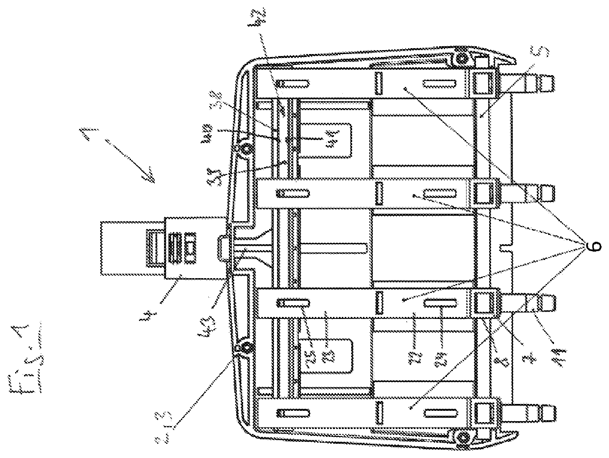
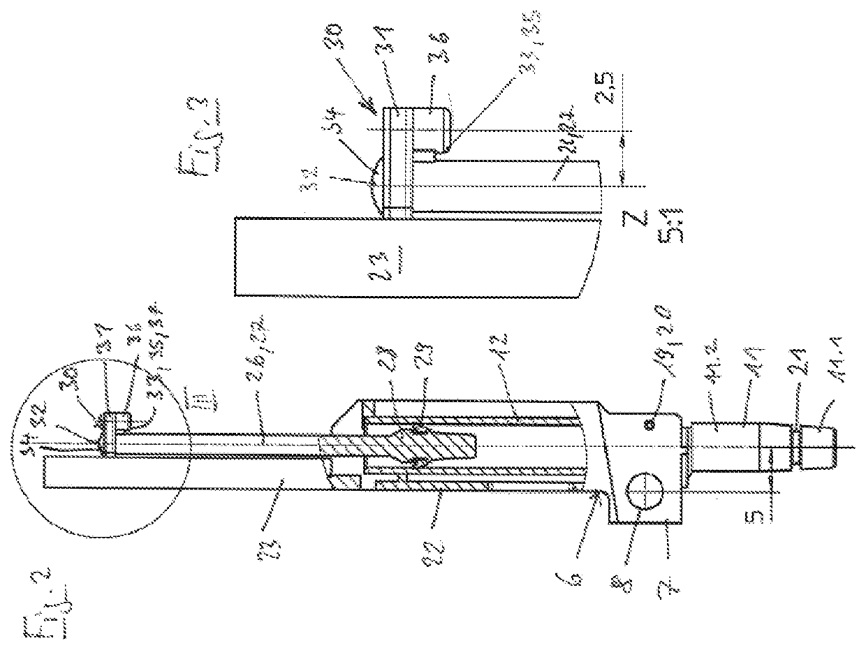
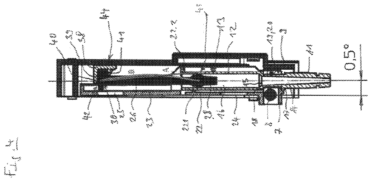
[0030]In the present application, the terms “at the top” and “at the bottom” as well as “side” or “lateral(ly)” relate to a multichannel pipetting head which is oriented vertically with the plunger-cylinder units and in which the drive rod is arranged above the necks.

[0031]According to FIGS. 1 to 3, the multichannel pipetting head 1 comprises a support structure 2 formed of a two-part housing 3. In FIG. 1, a front housing part has been removed such that only a rear housing part is shown. Alternatively, the support structure may also be formed of a chassis that is clad with a housing.

[0032]The housing 3 is substantially box-shaped. A fastening neck 4 for connection to a pipette top part projects vertically upward on the upper edge of the housing 3. A horizontal shalt 5 having a circular cross-section is held in the housing. Multiple guides 6 (in example 4) are held on. the shaft 5 so as to he movable in the horizontal direction and pivotable about the shaft 5.

[0033]According to FIG. ...


PUM


Abstract

A multichannel pipetting head comprises a plunger actuator comprising at least one groove with an upper border, and a lower border. A plurality of plunger-cylinder units, wherein each plunger-cylinder unit comprises a cylinder and a plunger comprising a plunger head. The plunger head comprises a projecting upper abutment region adjoining the upper border, a projecting lower abutment region adjoining the lower border and laterally offset relative to the projecting upper abutment region, a plurality of guides. Each of the cylinders is coupled to a neck and held on each of the plurality of guides. During lateral movement of the plurality of guides, the plunger head is configured to tilt in the groove and to be held with the upper abutment region abutting the upper border and with the lower abutment region abutting the lower border of the groove due to restoring forces that occur during tilting in the plunger-cylinder units.

Description

CROSS REFERENCE TO RELATED INVENTION[0001]This application is based upon and claims priority to, under relevant sections of 35 U.S.C. § 119, European Patent Application No. 20 183 723.4, filed Jul. 2, 2020, the entire contents of which are hereby incorporated by reference.FIELD OF TECHNOLOGY[0002]The invention relates to a multichannel pipetting head comprising multiple necks configured be moved relative to one another for clamping pipette tips.BACKGROUND[0003]Multichannel pipettes are used particularly in laboratories for simultaneously pipetting multiple liquid samples. The liquid samples are taken up from a row of receptacles in a microtiter plate or from other vessels into pipette tips that are releasably connected to the multichannel pipette and said liquid samples are dispensed from the pipette tips into vessels. Multichannel pipettes comprise multiple necks or shafts onto which the pipette tips can be clamped. One or more displacement apparatuses are provided for aspirating t...

Claims


Application Information

Patent Timeline
Patent Type & Authority Applications(United States)
IPC IPC(8): B01L3/02
CPCB01L3/0279B01L3/0234B01L3/021B01L3/0217B01L2200/022B01L3/0227
Inventor WILTH, MARCLINK, HOLGER
Owner EPPENDORF SE
Learn More