
Cognitive architecture for wideband, low-power, real-time signal denoising

a wideband, real-time signal technology, applied in the field of signal denoising system, can solve the problems of high-rate adcs, high computational complexity, high cost and power consumption,

Active Publication Date: 2018-12-11
HRL LAB
View PDF8 Cites 5 Cited by
  • Summary
  • Abstract
  • Description
  • Claims
  • Application Information

AI Technical Summary

Benefits of technology

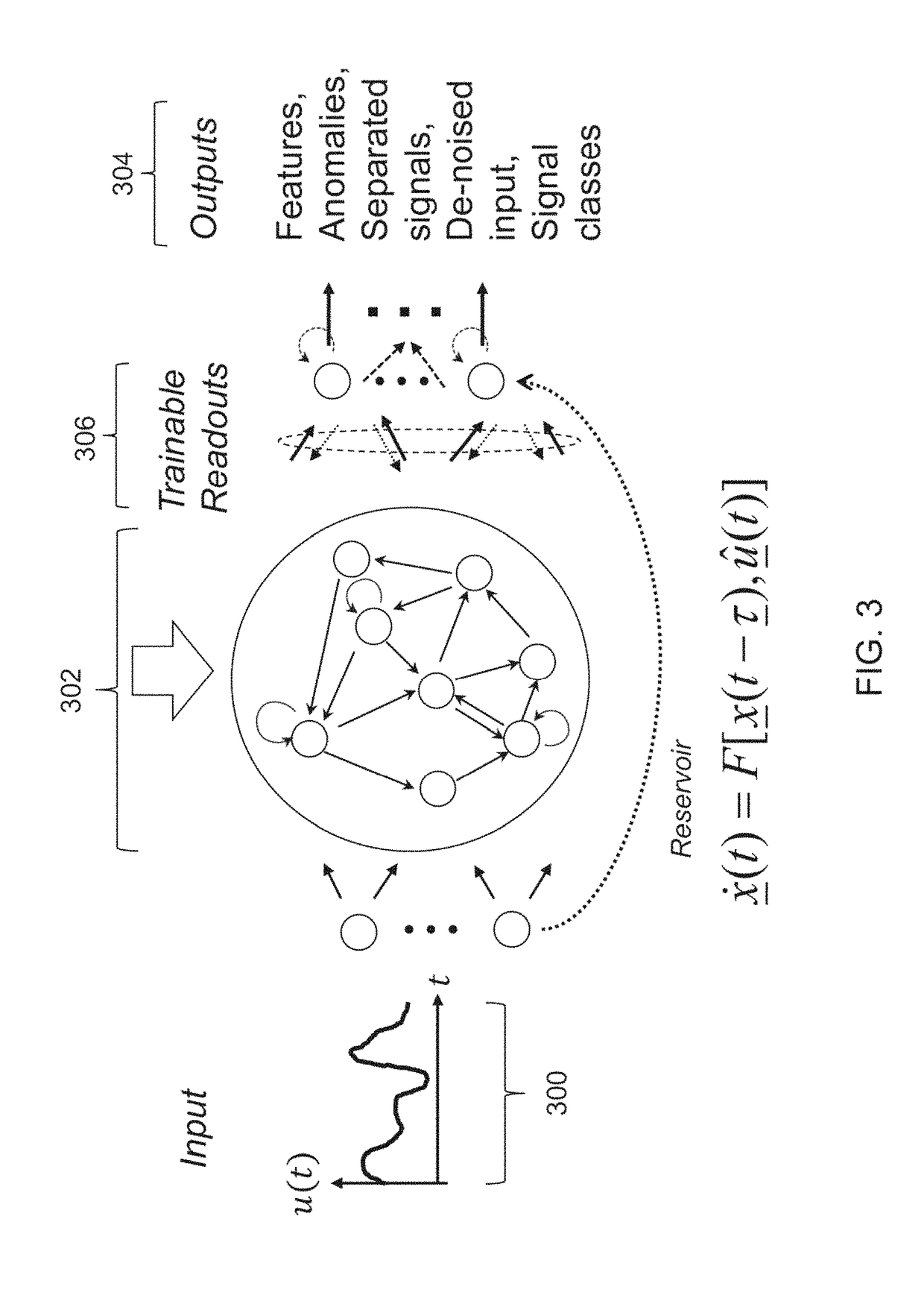
The present invention is a system for denoising signals that contain a mixture of waveforms over an ultra-wide bandwidth. The system uses a reservoir computer to map the input signals onto the states of a dynamic reservoir and adapt the output layer weights using short-time linear prediction. The system can be used in real-time and is utilized in various fields such as electromagnetic and acoustic signals. The invention includes a computer program product and computer implemented method for generating the predicted input signal and iteratively adapting the output layer weights. The technical effects of the invention include improved signal quality, improved denoising performance, and a wide range of applications.

Problems solved by technology

Such high-rate ADCs are expensive and power hungry; due to fundamental physical limits (such as the Walden curve described in Literature Reference No. 6 of the List of Incorporated Literature References), they are not capable of achieving the sampling rate needed to capture the ultra-wide bandwidth.
In addition, the detection, localization, and classification algorithms used in state-of-the-art ESM systems are typically based on the fast Fourier transform, with high computational complexity and memory requirements that make it difficult to operate them in real-time over an ultra-wide bandwidth.
Filter-based methods use filtering to smooth out noise from a signal, but are too simplistic to simultaneously maintain the low-frequency long-term trends of a signal while adapting to the high-frequency abrupt transitions.
In addition, the dictionary often requires a large amount of memory and computation to be stored and leveraged on the platform, making such approaches infeasible for ultra-low SWaP (size, weight, and power) systems.

Method used


Image

  • Cognitive architecture for wideband, low-power, real-time signal denoising
  • Cognitive architecture for wideband, low-power, real-time signal denoising
  • Cognitive architecture for wideband, low-power, real-time signal denoising

Examples


Embodiment Construction

[0028]The present invention relates to a system for signal denoising and, more particularly, to a system for denoising a signal that contains a mixture of waveforms over an ultra-wide bandwidth.

[0029]The following description is presented to enable one of ordinary skill in the art to make and use the invention and to incorporate it in the context of particular applications. Various modifications, as well as a variety of uses in different applications will be readily apparent to those skilled in the art, and the general principles defined herein may be applied to a wide range of aspects. Thus, the present invention is not intended to be limited to the aspects presented, but is to be accorded the widest scope consistent with the principles and novel features disclosed herein.

[0030]In the following detailed description, numerous specific details are set forth in order to provide a more thorough understanding of the present invention. However, it will be apparent to one skilled in the a...


PUM


Abstract

Described is a cognitive signal processor that can denoise an input signal that contains a mixture of waveforms over a large bandwidth. Delay-embedded mixture signals are generated from a mixture of input signals. The delay-embedded mixture signals are mapped with a reservoir computer to reservoir states of a dynamical reservoir having output layer weights. The output layer weights are adapted based on short-time linear prediction. Finally, a denoised output of the mixture of input signals is generated.

Description

CROSS-REFERENCE TO RELATED APPLICATIONS[0001]This is a Continuation-in-Part Application of U.S. Non-Provisional application Ser. No. 15 / 073,626, filed on Mar. 17, 2016, entitled, “Cognitive Blind Source Separator,” which is a Non-Provisional Application of U.S. Provisional Patent Application No. 62 / 135,539, filed on Mar. 19, 2015, entitled, “Cognitive Blind Source Separator,” the entirety of which are incorporated herein by reference.[0002]This is ALSO a Non-Provisional Application of U.S. Provisional Patent Application No. 62 / 304,623, filed Mar. 7, 2016, entitled, “Cognitive Architecture for Wideband, Low-Power, Real-Time Signal Denoising”, the entirety of which is incorporated herein by reference.STATEMENT REGARDING FEDERALLY SPONSORED RESEARCH OR DEVELOPMENT[0003]This invention was made with government support under U.S. Government Contract Number N00014-12-C-0027. The government has certain rights in the invention.BACKGROUND OF INVENTION(1) Field of Invention[0004]The present in...

Claims


Application Information

Patent Timeline
IPC IPC(8): H04B1/00H04B1/7163H04B1/719
CPCH04B1/719H04B1/71632G06N3/08G06N3/044G06F2218/04G06F2218/22G06F18/2134G06F18/24
Inventor PETRE, PETERRAO, SHANKAR R.
Owner HRL LAB
Learn More