
System calibration in an MR system

Active Publication Date: 2018-12-11
SIEMENS HEALTHCARE GMBH
View PDF9 Cites 0 Cited by
  • Summary
  • Abstract
  • Description
  • Claims
  • Application Information

AI Technical Summary

Benefits of technology

[0007]An object of the present invention is to provide a method for carrying out calibration measurements that is accelerated compared to known methods.
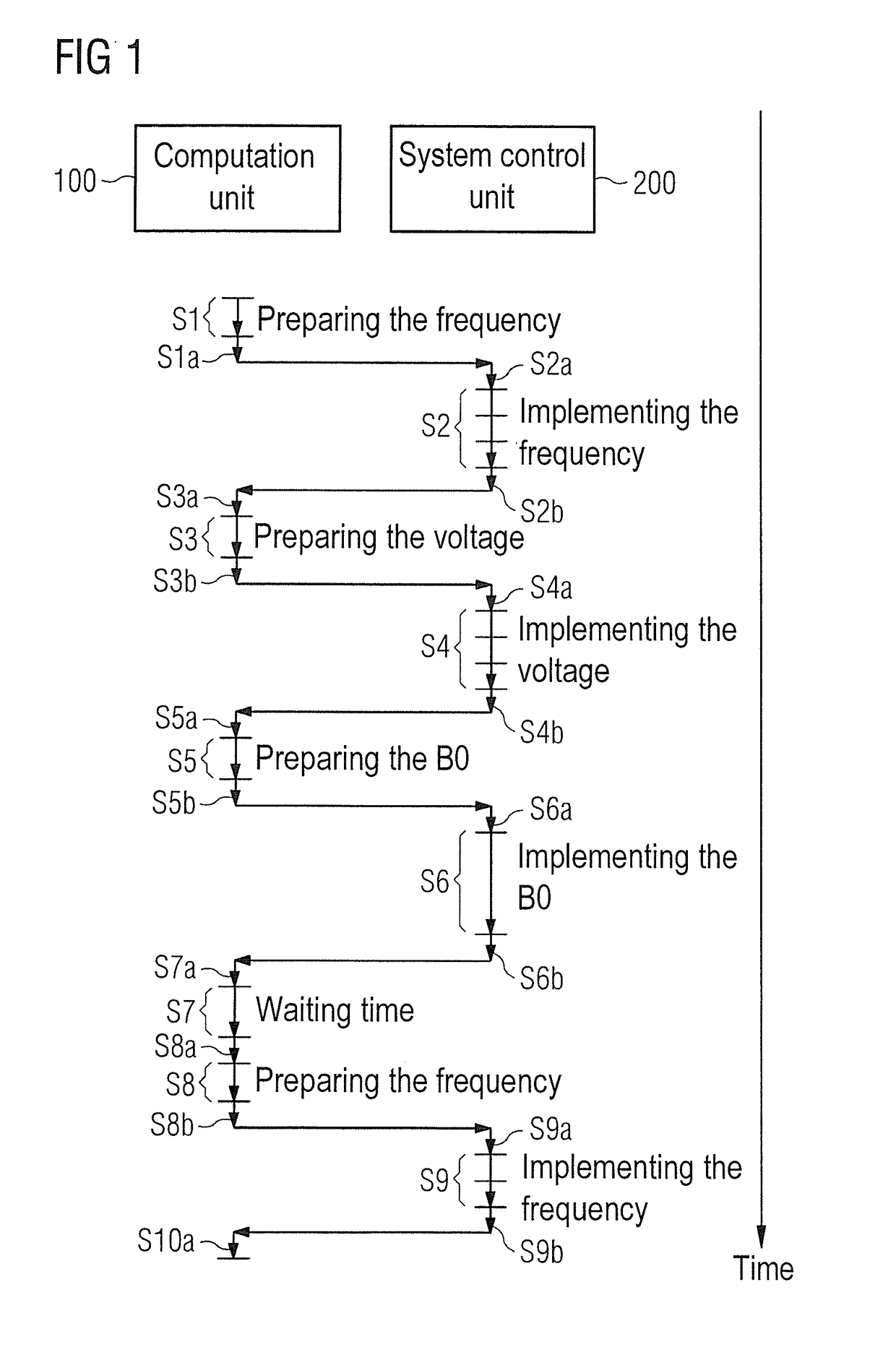
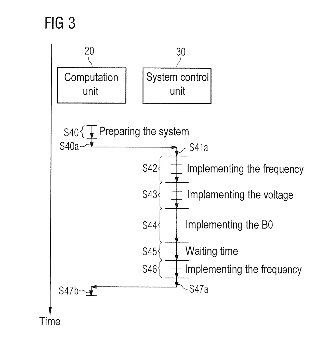
[0009]This means that the individual calibration steps are prepared in a single preparation step. This leads to a saving of time since, inter alia, less communication is necessary between the computer and the system control computer. Furthermore, the procedure is easier to plan since less communication is necessary between the computer and the system control computer. The duration of this communication cannot be determined beforehand. Since overall there are fewer steps that have an indefinite duration, the adjustment steps are easier to predict.
[0015]Preferably, all the calibration steps that are necessary before carrying out an MR measurement to acquire an MR image are prepared in a single preparation step, such that all the calibration steps can be carried out after this without the computer having to be involved in the meantime before the end of the calibration step.

Problems solved by technology

The individual preparation phases and time delays that result inter alia from communication between the two units extend the overall time required for the calibration measurements.

Method used


Image

  • System calibration in an MR system
  • System calibration in an MR system
  • System calibration in an MR system

Examples


Embodiment Construction

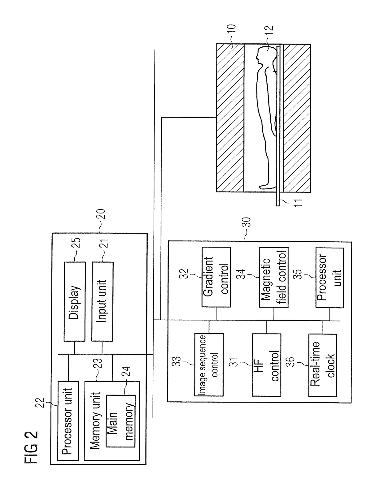
[0021]FIG. 2 shows a black diagram of an MR system with which, as will be explained in detail, calibration measurements can be carried out in a time-optimized manner. The MR system has a scanner with a magnet 10 for generating a polarization field B0, an examination subject 12 arranged on a bed 11 being moved into the MR scanner or into the magnet 10 in order to acquire data for MR images of a partial area of the examination subject 12. The MR system has a computer 20, with which an operator can operate and control the MR system. The computer 20 has an input unit (interface) 21, via which the operator can make inputs, such as, for example, the selection of imaging sequences or the positioning of slices. A processor 22 is provided for control of the computer. In a memory unit 23 there are, together with pre-stored imaging sequences, program files, which initiate calibration steps in a system control computer 30 when they are carried out in the processor 22. The memory unit 23 has a m...


PUM


Abstract

In a method for making calibration measurements in a magnetic resonance (MR) system, in order to acquire an MR image of an examination subject, wherein the MR unit has a computer for operating the MR scanner, and a system control computer designed to control multiple system components of the MR scanner, a preparation step is executed by the computer to prepare a first calibration step, in which a first parameter of a system component is matched to the examination subject via the system control computer, and to prepare a second calibration step, in which a second parameter of a system component is matched to the examination subject via the system control computer. The first calibration step is executed by the system control computer as is the second calibration step. The preparation step is executed by the computer to prepare one of the first or second calibration steps before one of the calibration steps is initiated by the system control computer.

Description

BACKGROUND OF THE INVENTION[0001]Field of the Invention[0002]The present invention concerns a method for carrying out calibration measurements in an MR system, as well as an MR system for implementing such a method.[0003]Description of the Prior Art[0004]In MR systems, in order to acquire an MR image, the MR signals must be acquired using system parameters such as the resonance frequency, transmitter reference amplitude, or the polarization field B0, have to be adjusted to the test subject in order to be able to obtain meaningful MR images of the test subject. In order to determine the parameters for these system components, a stand-alone calibration step is carried out in each case. This usually involves a specific stand-alone MR measurement and an evaluation provided therefor. Within such an MR measurement, which is carried out in a system control computer, the time schedule can be set and carried out in the sub-microsecond range. This is relevant, for example, when the calibratio...

Claims


Application Information

Patent Timeline
Patent Type & Authority Patents(United States)
IPC IPC(8): G01R33/58G01R33/3875G01R33/54
CPCG01R33/583G01R33/543G01R33/546G01R33/3875
Inventor CAMPAGNA, SWENWULLENWEBER, MICHAEL
Owner SIEMENS HEALTHCARE GMBH
Learn More