Wire harness

a wire harness and wire technology, applied in the direction of insulated conductors, cables, coupling device connections, etc., can solve the problems of insulator will fracture in some cases, and achieve the effects of high storage modulus, reduced insulator prone to fracture, and sufficient flexibility

Active Publication Date: 2018-12-04
AUTONETWORKS TECH LTD +2
View PDF11 Cites 0 Cited by
  • Summary
  • Abstract
  • Description
  • Claims
  • Application Information

AI Technical Summary

Benefits of technology

[0005]The present disclosure is made in light of the above-described circumstances, and provides a wire harness in which cracks and fracturing are unlikely to appear in the insulator due to vibration, without impairing the flexibility of an electric wire.
[0008]In the above-described wire harness, the insulator has a storage modulus E′ of 100 MPa or less at 25° C., and thus even though an electric wire is bent under severe conditions, the electric wire exhibits sufficient flexibility.
[0009]Also, in the above-described wire harness, the insulator has a storage modulus E′ of 1 MPa or more at 250° C., and thus deformation of the insulator inward in the diameter direction is suppressed in a high temperature environment during insert molding, and a portion that cuts into the insulator is unlikely to be formed in the molded resin portion. Therefore, with the above-described wire harness, it is possible to suppress the appearance of cracks in the insulator and fracturing of the insulator even though vibration is applied in the state in which the electric wire is bent.
[0010]Also, in the above-described wire harness, the starting temperature of the rubbery plateau region in the storage modulus E′ of the insulator is 150° C. or less. Thus, even in the case where the temperature received by the insulator from resin that flows during insert molding varies depending on the location of the molded resin portion, locations with a high storage modulus E′ or the like are unlikely to be formed in parts of the insulator. Therefore, with the above-described wire harness, a cutting-in portion that significantly cuts into the insulator is unlikely to form in the molded resin portion, and it is possible to suppress the appearance of cracks in the insulator and fracturing of the insulator even though vibration is applied in the state in which the electric wire is bent.
[0011]Thus, according to the present disclosure, it is possible to provide a wire harness in which cracks and fracturing are unlikely to appear in the insulator due to vibration, without impairing the flexibility of an electric wire.

Problems solved by technology

If the portion that cuts into the insulator is formed in the molded resin portion, when the wire harness is used, cracks appear in the insulator due to vibration, and there is a risk that the insulator will fracture in some cases.
In particular, if vibration is applied in the state in which the electric wire is bent, the insulator tends to fracture.

Method used


Image

  • Wire harness
  • Wire harness
  • Wire harness

Examples


working examples

[0026]Hereinafter, wire harnesses of working examples will be described with reference to the drawings.

working example 1

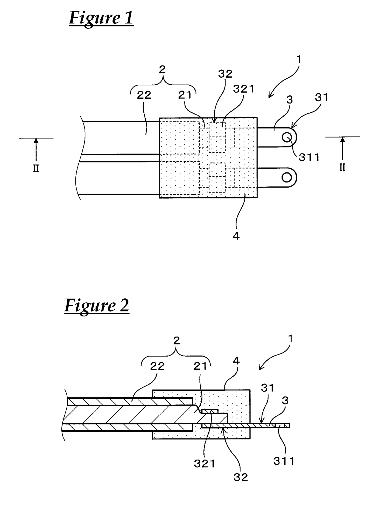
[0027]A wire harness of Working Example 1 will be described with reference to FIGS. 1 to 3. As shown in FIGS. 1 to 3, a wire harness 1 of this example has electric wires 2, terminals 3, and a molded resin portion 4. In this example, the wire harness 1 is used to connect an inverter and a motor in an automobile (not shown) provided with the inverter and the motor. Also, in the drawings, an example is shown in which the wire harness 1 has a plurality of electric wires 2 and a plurality of terminals 3.

[0028]The electric wires 2 each include a conductor 21 and an insulator 22 that coats an outer periphery of the conductor 21. In this example, the conductor 21 is constituted by a twisted wire obtained by twisting a plurality of wires (not shown). The wire is made of a copper alloy plated with tin. The cross-sectional area of the conductor is 20 mm2. The insulator 22 is constituted by a crosslinked polyethylene. The thickness of the insulator 22 is 1.1 mm. The insulator 22 is removed from...

experimental examples

Production of Samples

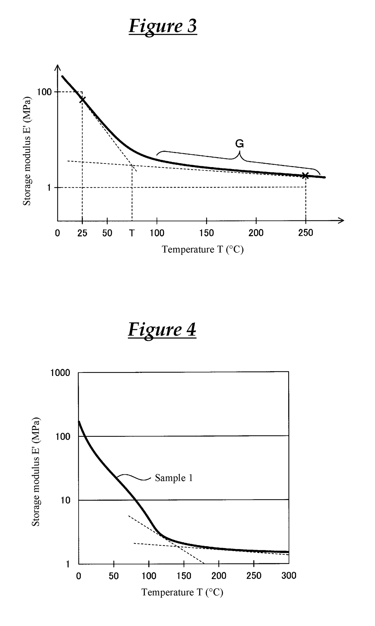
[0033]As shown in Table 1, electric wires that were coated with insulators whose moduli have different properties (different storage moduli E) and that had terminals crimped to their terminal ends were prepared. The cross-sectional area of the conductors of the electric wires was 20 mm2. The insulators in Samples 1 to 4 and Samples 1C to 4C were all constituted by crosslinked polyethylene. The insulator in Sample 5 was constituted by silicone. Note that the property of the storage modulus E′ was changed by adjusting the type, the blending ratio, the degree of crosslinking, or the like of resins in the insulator formation materials. Also, a dynamic viscoelasticity measurement device “DMA2980” manufactured by TA Instruments was used to measure the storage modulus E. The measurement mode was a tensed mode, the temperature increase rate was 5° C. / min, and the frequency was 10 Hz. Also, the measurement atmosphere was air, and the measurement temperature range for the...


PUM

PropertyMeasurementUnit
temperatureaaaaaaaaaa

Abstract

A wire harness that includes an electric wire provided with a conductor and an insulator that coats an outer periphery of the conductor, a terminal connected to the conductor at a terminal end of the electric wire, and a molded resin portion that covers an outer periphery of the insulator at the terminal end of the electric wire and an outer periphery of an end portion on the electric wire side of the terminal. A storage modulus E′ of the insulator that is measured using a dynamic viscoelasticity measurement device in a tensed mode at a temperature increase rate of 5° C. / min and a frequency of 10. Hz is 100 MPa or less at 25° C. and 1 MPa or more at 250° C., and a starting temperature (T) of a rubbery plateau region (G) is 150° C. or less.

Description

CROSS REFERENCE TO RELATED APPLICATIONS[0001]This application claims the priority of Japanese patent application JP2015-238797 filed on Dec. 7, 2015, the entire contents of which are incorporated herein.TECHNICAL FIELD[0002]The present invention relates to a wire harness.BACKGROUND ART[0003]In recent years, wire harnesses for connecting an inverter and a motor have been used in automobiles such as hybrid cars and electric cars. As disclosed in Patent Document 1 (JP2015-133230A), for example, a wire harness including an electric wire provided with a conductor and an insulator that coats an outer periphery of the conductor, a terminal connected to the conductor at a terminal end of the electric wire, and a molded resin portion that covers an outer periphery of the insulator at the terminal end of the electric wire and an outer periphery of an end portion on the electric wire side of the terminal is known as this type of wire harness.SUMMARY[0004]When a wire harness is to be attached t...

Claims


Application Information

Patent Timeline
Patent Type & Authority Patents(United States)
IPC IPC(8): H01B7/00B60R16/02H01B3/44H01B3/42H01B3/30H01B7/02H01B3/46H02G1/14H01R4/70H01B7/24
CPCH01B7/24B60R16/0207H01B3/305H01B7/02H01B3/441H01B3/46H01B7/0045H01B3/423H01R4/70H02G1/14H01R13/5845
Inventor NAKASHIMA, KAZUOMATSUI, KATSUFUMIFUKUMOTO, KOUJITACHI, KENTARO
Owner AUTONETWORKS TECH LTD
Why Eureka
Try Eureka