
Adiabatic refrigerant condenser controls system

a technology of refrigeration condenser and controls system, which is applied in indirect heat exchangers, lighting and heating apparatus, heating types, etc., can solve the problems of reducing airflow through the unit, reducing the efficiency of water or energy resources, and prior art products having a penalty of pressure drop, etc., to achieve high demand, save electricity, and high demand resource

Active Publication Date: 2018-11-20
BALTIMORE AIRCOIL CO INC
View PDF19 Cites 17 Cited by
  • Summary
  • Abstract
  • Description
  • Claims
  • Application Information

AI Technical Summary

Benefits of technology

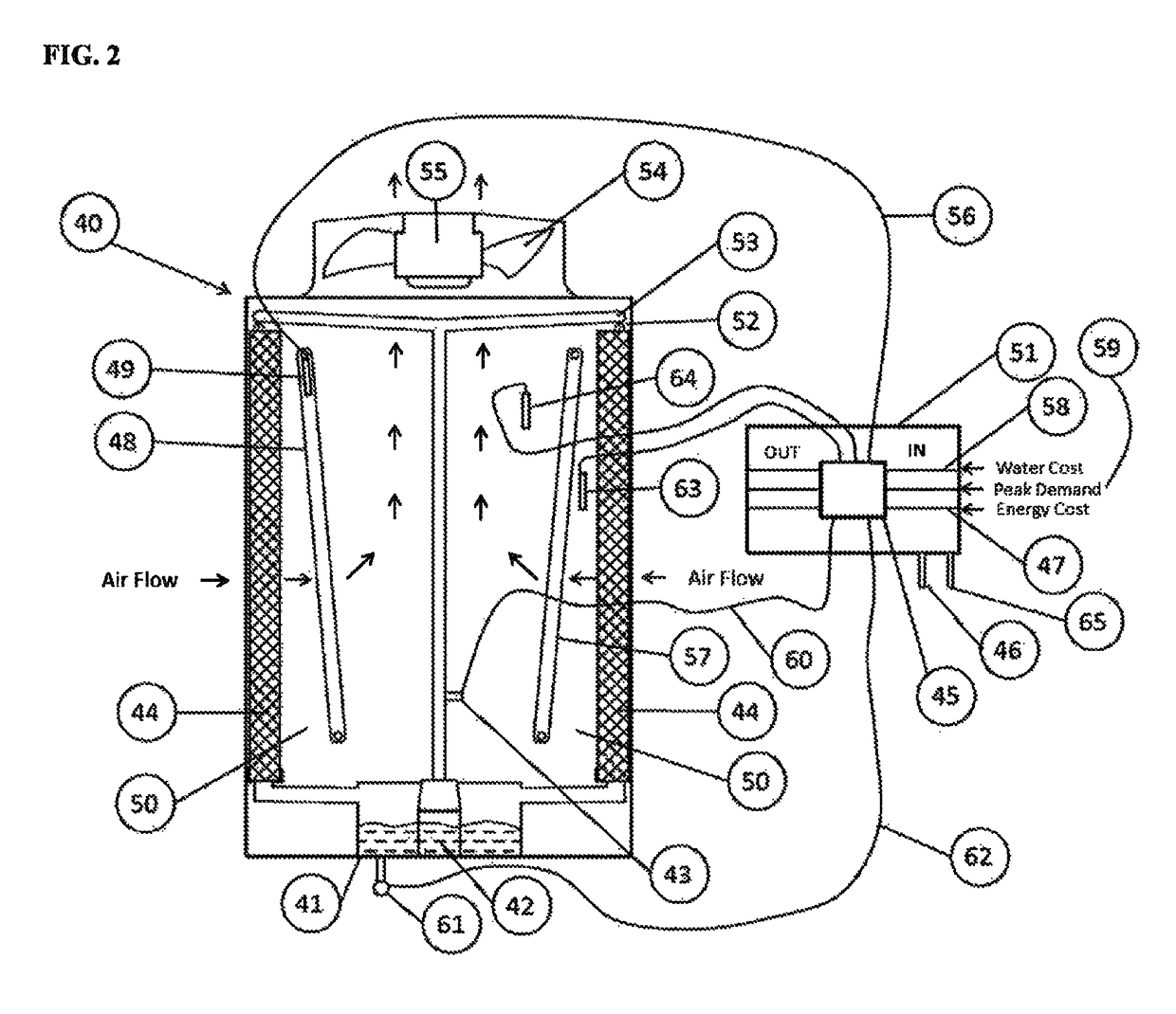
[0009]Two modes of operation are possible for the inventive system. The first mode is described as the energy savings mode. Prior art adiabatic operation is controlled by an outdoor temperature set point. When the outdoor temperature exceeds this set point, the wet mode is initiated regardless of whether it is needed or not. This method of control is referred to as standard mode. A new inventive energy savings mode is presented that, in order to save electrical energy usage, will turn the wet operation on as soon as the temperature is high enough to prevent water freezing on the adiabatic pads. With wet operation running at a much lower temperature than with the standard mode, cooler air will be entering the coil driving system head pressure lower than otherwise obtained without wet operation and the variable speed motor driven fans may run at a slower speed thereby reducing energy consumption from the compression system and / or cooler fans. Overall energy consumption is reduced when compared to the prior art standard mode.
[0010]The second mode of operation is the water savings mode. This method of control keeps wet operation off until it is necessary to meet the heat rejection requirement. Only once the capacity of the unit has been maximized in dry operation and the variable speed motor driven fans are at full speed (set point is adjustable), the wet cooling operation will be turned on to increase heat rejection capacity. Delaying the wet operation until absolutely necessary will minimize the amount of water used by the unit. Overall water consumption is reduced when compared to the prior art standard mode.
[0012]This invention also includes multiple methods for selecting the mode of operation. The most basic way is for the user to select the mode manually in the control system. There are also automated selection methods available. The control system can choose the mode of operation to minimize the energy usage. To do this, the control system needs inputs related to the cost for electricity and water. This information can either be entered manually into the control system, or it can be communicated electronically via a communications protocol. Once the control system has this information, it can calculate the cost of running in energy savings mode and water savings mode and determine which mode provides the lowest overall operating cost to the user. This decision can be continually updated based on changing cost information.
[0013]Another method for switching modes is to do so based on a peak demand signal from utility providers. This signal would let the unit know that either electricity or water is in high demand, and that the high demand resource should be conserved. For example, if the electric utility sent a peak demand signal, the controls could switch to energy savings mode to conserve electricity. This method of mode control helps to reduce the strain on utility systems. It also helps the user by lowering possible peak demand charges as much as possible.

Problems solved by technology

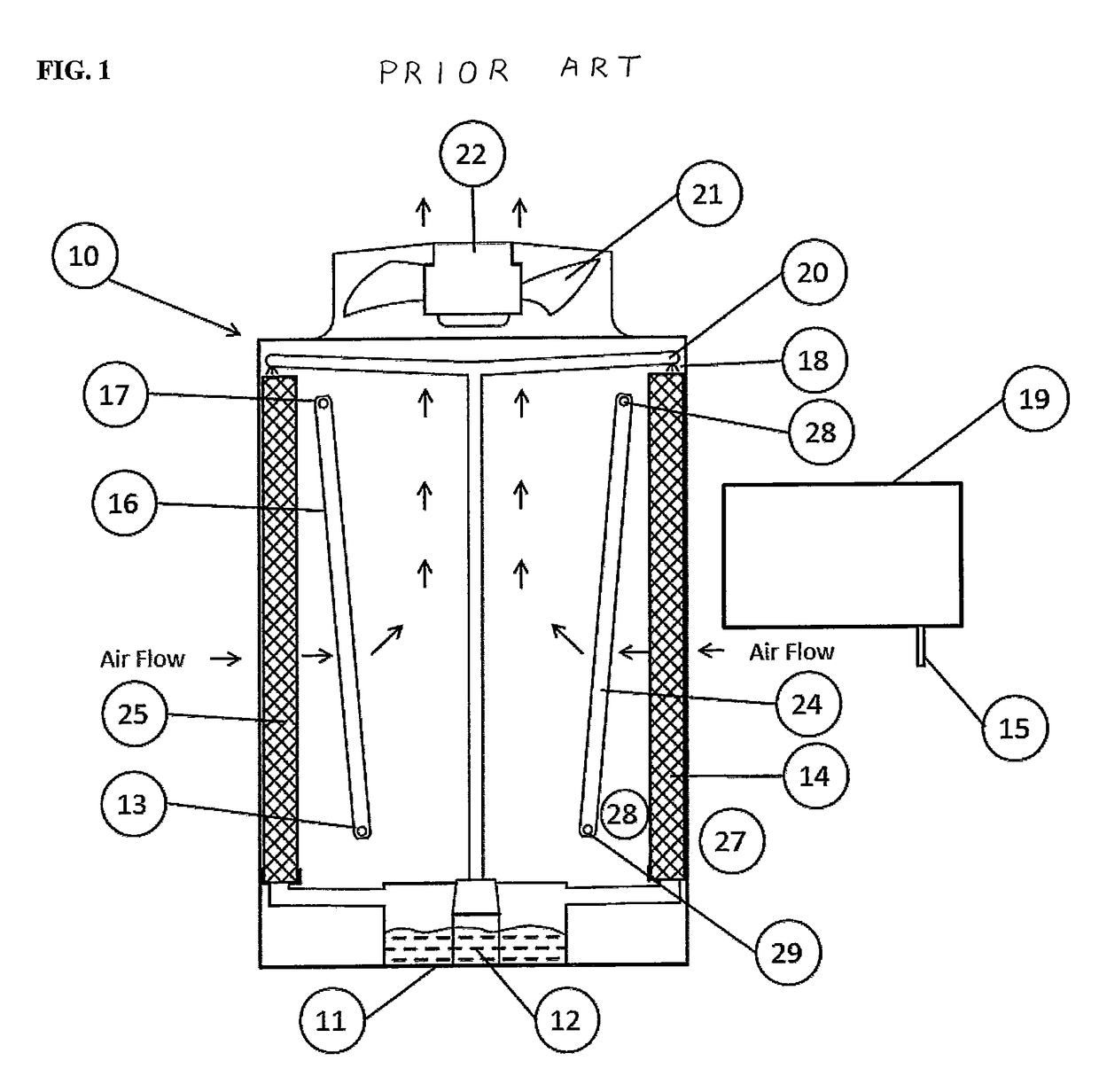
Typical prior art condensers or fluid coolers can switch from dry to wet operation at a certain preset outdoor temperature or preset temperature or pressure condition; however, the prior art systems do not allow the savings of either water or energy resource to be optimized.
If water is the scarcer or more costly resource, then the system will use water only when necessary to meet the heat rejection target.
When running in the dry mode, the prior art product has a penalty of pressure drop through the adiabatic pads and consequently having reduced airflow through the unit.

Method used


Image

  • Adiabatic refrigerant condenser controls system
  • Adiabatic refrigerant condenser controls system
  • Adiabatic refrigerant condenser controls system

Examples


embodiment 30

[0028]FIG. 3, shows an improved adiabatic condenser or fluid cooler embodiment 30 which includes a coil cleaning mode. In this embodiment, the airflow may be reversed so it enters through the fan 35 generally downward and is pushed out through the coils 34 and 39 so as to force accumulated dirt deposits back out of the coils. There may also be coil spray washers 33 inside of the unit to spray water directly onto and through coil 34 to assist in washing the accumulated dirt and debris off of coils 34 and 39. A water connection point 31 and a water valve 32 with control wire 37 are provided so fresh water can be piped to the spray washers 33 and controlled selectively with the fan 35 running backwards by reversing motor 36 via controller 38. The coil cleaning mode may run during the cooling mode or can run when there is no demand for cooling.

[0029]FIG. 4, shows embodiment of an adiabatic condenser or fluid cooler 70 which includes swing away adiabatic pads 74 (shown open) and 82 (show...

embodiment 90

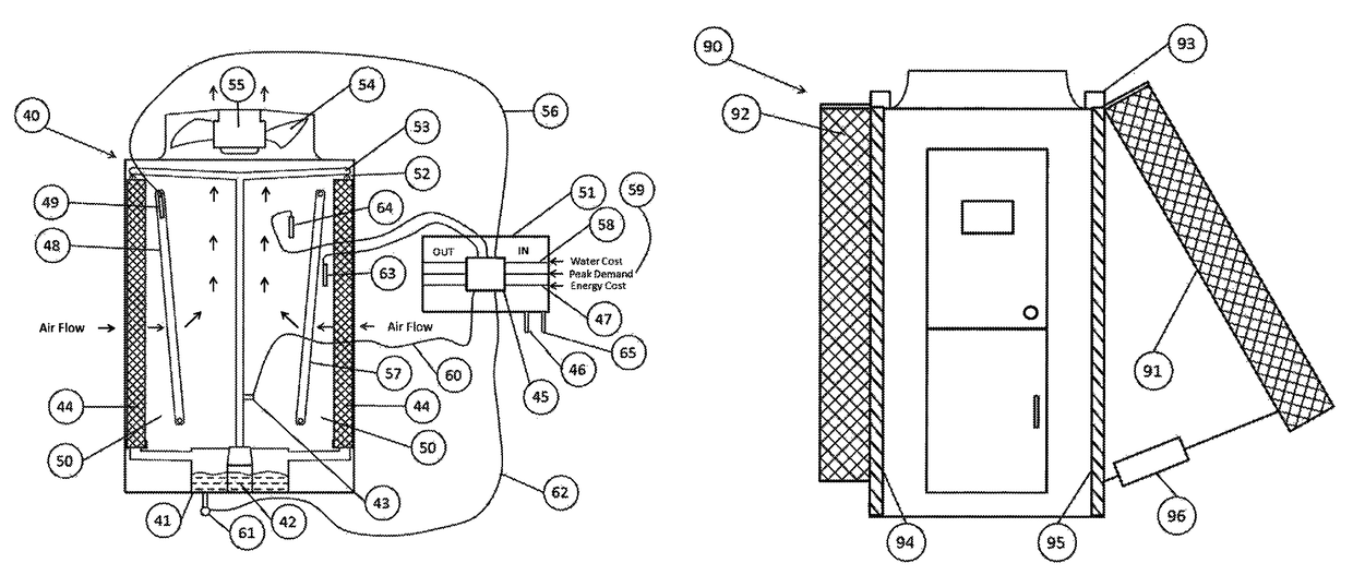
[0030]FIG. 5, is another embodiment of an adiabatic condenser or fluid cooler 90 showing swing away pads 91 that shows the pads lifting up out of the way (gull-wing design). In this embodiment, adiabatic pads 91 may be swung away from coils 94 and 95 by piston actuator 96. Adiabatic pads 92 are shown in the closed operating mode. Hinge 93 keeps the top of adiabatic pads connected to embodiment 90.

[0031]FIG. 6, shows another embodiment of an adiabatic condenser or fluid cooler 100 that allows the bypass of a majority of outdoor ambient air around adiabatic pads 102 when desired. In this embodiment, adiabatic pads are moved further away from the coils 106 and 107 such that air bypass louvers 104 may be installed and selectively operated by controller 108. During the air bypass mode, air bypass louvers 104 may be selectively opened allowing fresh air to directly enter into coils 106 and 107 through openings 103. FIGS. 4, 5 and 6 show embodiments to bypass fresh air around the adiabatic...


PUM


Abstract

An adiabatic condenser or fluid cooler is provided. A condensing or fluid cooling coil is provided. An adiabatic pad is provided wherein water can be used to cool the ambient air before entering or impacting the condensing or fluid cooling coil. Controls are provided that can adjust or eliminate the amount of water flowing over the adiabatic pad. The adiabatic pad may also be physically moved to allow ambient air to directly impact the condensing or fluid cooling coil.

Description

BACKGROUND OF INVENTION[0001]This invention relates to improvements in the design of an adiabatic condenser or fluid cooler. More specifically this details two new control modes; energy savings mode and water savings mode; which are designed to optimize the use of these resources based on cost and availability. This invention may be applied to units employing adiabatic saturation pads and also applied to units that employ any means to evaporate water (such as spray nozzles) before an indirect coil to reduce and cool the entering air temperature to the indirect coil.[0002]Prior art adiabatic control systems use a combination of water and electrical energy to provide the necessary cooling required. Electrical energy is used to drive the fans, which moves air through the coil(s). Water is used to wet the adiabatic material and lower the temperature of the air passing through the coil. This prior art system saves energy over an air cooled system and saves water over an evaporative syste...

Claims


Application Information

Patent Timeline
Patent Type & Authority Patents(United States)
IPC IPC(8): F25B39/04F28C1/14F28B11/00F28B9/06F28B9/04F24F3/00F28D5/00F28C3/08F28F27/00F28F27/02F28D1/02F24F5/00F24F13/22F24F1/00F24F1/0059
CPCF28F27/02F28B9/04F28B9/06F28B11/00F28C1/14F28C3/08F28D1/024F28D5/00F28F27/00F28F27/003F24F3/001Y02B30/748F24F5/0035F24F2001/0092F24F2013/225F25B2339/041F25B2339/047F24F1/0007F24F1/0059F28D2021/0063Y02B30/54Y02B30/70
Inventor MARTELL, GREGSHEER, ADAMHOLLANDER, PHILIPBLAY, PRESTONAARON, DAVID ANDREW
Owner BALTIMORE AIRCOIL CO INC
Learn More