
Portable lighting device with thermoelectric power source

a technology of thermoelectric power source and portable lighting, which is applied in the field of portable lighting devices with thermoelectric power source, can solve the problems of low low power generation capacity, and short circuit of electrical energy source, so as to increase the thermoelectric power generation efficiency of thermoelectric power generation, increase the level of practical application, and compact size

Active Publication Date: 2018-10-30
HLC GLOBAL PTE LTD
View PDF13 Cites 0 Cited by
  • Summary
  • Abstract
  • Description
  • Claims
  • Application Information

AI Technical Summary

Benefits of technology

The present invention provides an innovative thermoelectric lighting device that has a high thermoelectric power generation capacity, a high power generation efficiency, and is very convenient to carry. The device uses a compact design with a thermoelectric power generation chip, a light emitting unit, a heat dissipation unit, and a heat supply unit, solving technological problems and greatly increasing the level of practical application in the market for thermoelectric lighting devices. Additionally, the device has a portable design, making it convenient for practical application in various situations.

Problems solved by technology

With the increasingly scarcity of the world's energy sources, the widespread application of electrical energy powered lighting will lead to the demanding supply of electrical energy sources, and especially during the summer peak period, the seriously shortage of electrical energy source may even affect the everyday lighting need of people.
However, light apparatus in the existing technologies is far from practical application in the market.
This type of thermoelectric lighting apparatus in the existing technologies, in general, has the following major drawbacks: the thermoelectric power generation efficiency is low and the power generation capacity is low.
In the existing technology, there is no solutions to solve the above problems, which is the solution to maintain a relatively large temperature differences between the two sides of the thermoelectric power generation chip.
This leads to the light apparatus in the existing technologies fails to provide lighting to meet the actual application need.
In addition, the instability of temperature differences also makes it difficult to provide a stable lighting output in actual use.
However, this type of improvement will lead to the entire lighting apparatus to have a huge size and the cost effectiveness is even lower than lighting by using electricity directly.

Method used


Image

  • Portable lighting device with thermoelectric power source
  • Portable lighting device with thermoelectric power source
  • Portable lighting device with thermoelectric power source

Examples


Embodiment Construction

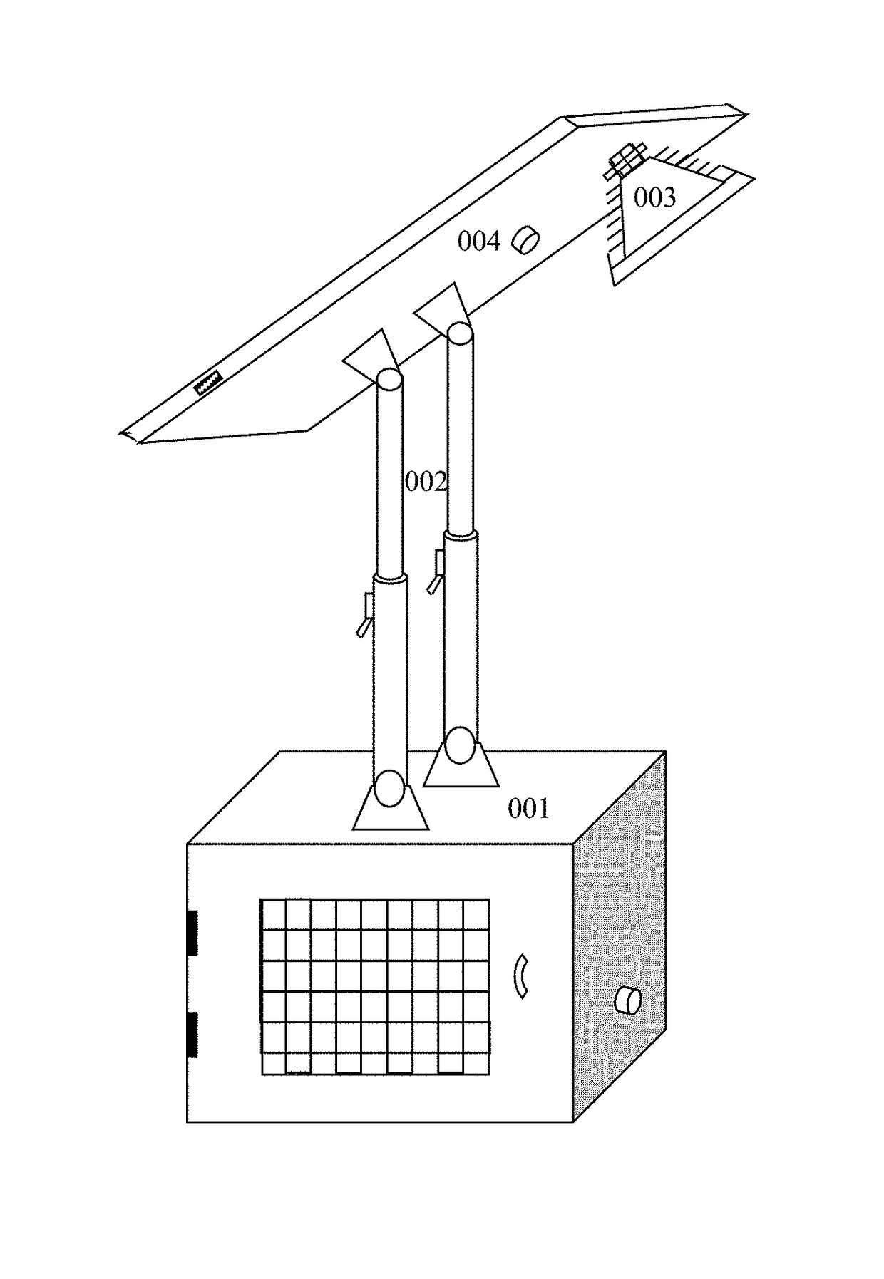
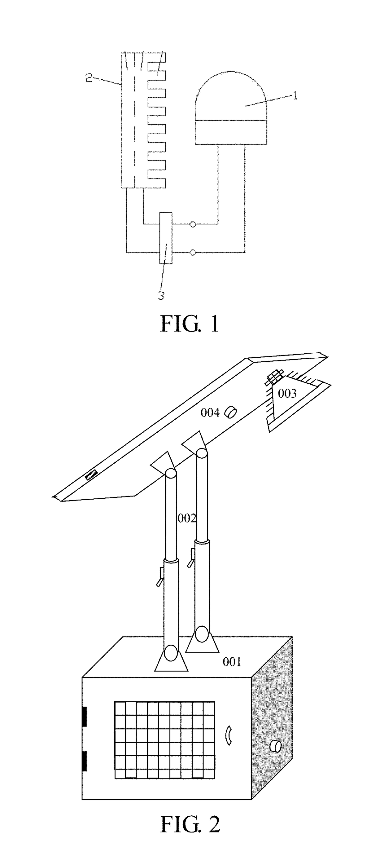
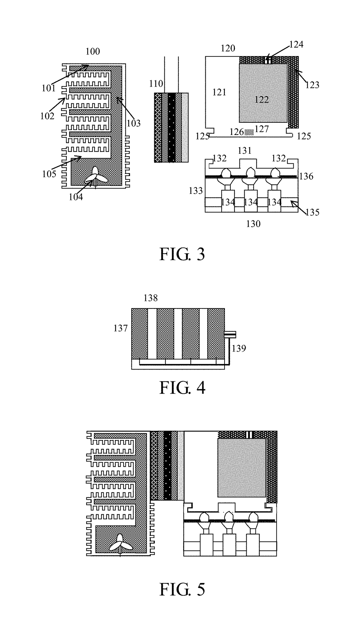
[0041]Referring to FIG. 2 of the drawings, the overall design of a thermoelectric lighting device according to the preferred embodiment of the present invention includes a thermoelectric power generation module 001, an adjustment rod 002, a light emitting unit 003 and a mounting top panel 004, wherein the light emitting unit 003 is mounted onto a surface of the mounting top panel 004, the mounting top panel 004 and the thermoelectric power generation module 001 are connected through the adjustment rod 002, the adjustment rod 002 has a bottom end connected to a top surface of a body of the thermoelectric power generation module 001 through rotary shaft connection, the adjustment rod 002 has a top end connected to an inner surface of the mounting top panel 004 through rotary shaft connection, while the adjustment rod 002 is capable of extending along its length for length adjustment such that an illumination direction of the light emitting unit 003 can be adjusted freely, the illumina...


PUM


Abstract

A lighting device which includes a light emitting unit, a thermoelectric power generation module for powering the light emitting unit, a top panel supporting the light emitting unit, and an adjustment rod connecting the thermoelectric power generation module with the top panel. The thermoelectric power generation module features hot and a cold sides, includes a heat dissipation unit proximal to the cold side, a thermoelectric power generation chip set, a heat supply box proximal to the hot side and a combustion chamber connected to the heat supply box.

Description

CROSS REFERENCE TO RELATED APPLICATION[0001]This is a national phase national application of an international patent application number PCT / CN2014 / 078880 with a filing date of May 30, 2014, which claimed priority of one foreign application in China: application number 201310219930.1 and filing date Jun. 4, 2013. The contents of these specifications, including any intervening amendments thereto, are incorporated herein by reference.BACKGROUND OF THE PRESENT INVENTION[0002]Field of Invention[0003]The present invention relates to a lighting technology, and more particularly to a portable lighting device based on principle of thermoelectric power generation.[0004]Description of Related Arts[0005]In our social reality, lighting has already become a necessity for people's lives. At present, the majority of lighting devices are based on power generation from electricity. With the increasingly scarcity of the world's energy sources, the widespread application of electrical energy powered li...

Claims


Application Information

Patent Timeline
Patent Type & Authority Patents(United States)
IPC IPC(8): F21L13/00F21V23/00F21V23/04H01L35/16F21V29/90H01L35/30F21S9/04H01L35/32H01L35/18F21V29/74F21V29/58F21V29/70H10N10/17F21Y115/10H10N10/13H10N10/852H10N10/853
CPCH01L35/32F21L13/00F21S9/04F21V23/003F21V23/0414F21V29/58F21V29/74F21V29/90H01L35/16H01L35/18H01L35/30F21V29/70F21Y2115/10H10N10/852H10N10/853H10N10/13H10N10/17
Inventor FENG, CHAOHUI
Owner HLC GLOBAL PTE LTD
Learn More