Passive safety equipment for a nuclear power plant

a safety equipment and nuclear power plant technology, applied in nuclear reactors, nuclear elements, greenhouse gas reduction, etc., can solve the problems of increasing the size of the heat exchanger, reducing safety, and low economics, so as to increase the efficiency of cooling an inside, promote natural circulation, and reduce the boundary of the exclusion area

Active Publication Date: 2018-10-30
KOREA ATOMIC ENERGY RES INST
View PDF9 Cites 4 Cited by
  • Summary
  • Abstract
  • Description
  • Claims
  • Application Information

AI Technical Summary

Benefits of technology

[0015]An object of the present disclosure is to propose a passive safety facility with an enhanced cooling performance within the containment using a facility which can overcome the limitation of the natural circulation, and a nuclear power plant including the same.
[0040]According to the present disclosure having the foregoing configuration, it may be possible to promote natural circulation using a circulation inducing jet device to increase an efficiency of cooling an inside of the containment, thereby overcoming the technical limitation of the related art depending on natural circulation within the containment.
[0041]Furthermore, the present disclosure may induce the second fluid within the containment at the same time to the heat exchanger by the discharge flow of the first fluid, thereby solving the problems of size increase, cost increase and safety degradation in the heat exchanger for cooling the containment in a nuclear power plant.
[0042]In addition, the present disclosure may reduce a concentration of radioactive materials within the containment at an early stage using a filter facility. As the concentration of radioactive materials is reduced, the present disclosure may decrease the exclusion area boundary.

Problems solved by technology

However, it is preferable to adopt the reinforced concrete-type containment building rather than the steel containment applied to the related art due to difficulties in manufacturing and maintenance, low economic efficiency, and the like.
In such a configuration where natural convection is dominant, the heat transfer coefficient on a surface over which the atmosphere (air and steam) flows is very small, thereby causing a problem in which the size of the heat exchanger should be greatly increased.
Meanwhile, the heat exchanger may be a structure of forming a pressure boundary of the containment, thus a possibility of the pressure boundary break may increase when the size of the heat exchanger increases, thereby causing a problem of decreasing the safety.

Method used


Image

  • Passive safety equipment for a nuclear power plant
  • Passive safety equipment for a nuclear power plant
  • Passive safety equipment for a nuclear power plant

Examples


Embodiment Construction

[0071]Hereinafter, a passive safety facility and a nuclear power plant including the same associated with the present disclosure will be described in more detail with reference to the accompanying drawings. Even in different embodiments according to the present disclosure, the same or similar reference numerals are designated to the same or similar configurations, and the description thereof will be substituted by the earlier description. Unless clearly used otherwise, expressions in the singular number used in the present disclosure may include a plural meaning.

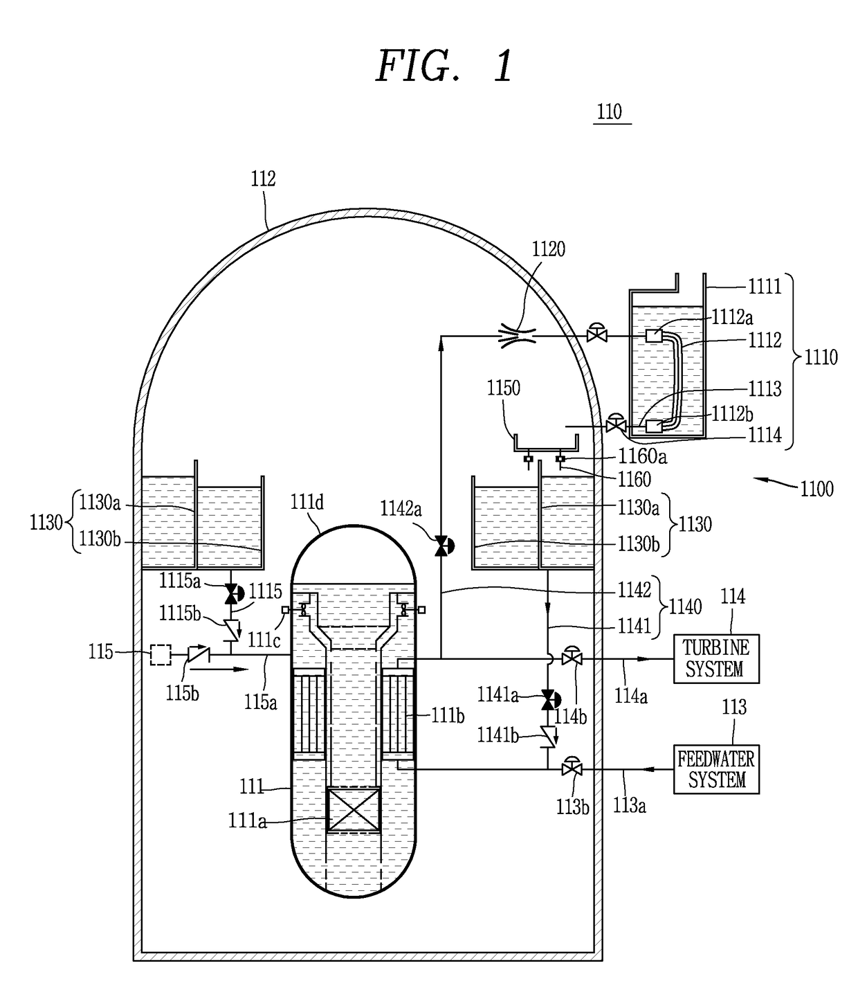
[0072]FIG. 1 is a conceptual view illustrating when a normal operation is carried out on a passive safety facility 1100 and a nuclear power plant 110 including the same associated with an embodiment of the present disclosure.

[0073]The nuclear power plant 110 may include a reactor coolant system 111, a containment 112 and a passive safety facility 1100.

[0074]A core 111a and a steam generator 111b are provided within the react...


PUM


Abstract

The present invention provides passive safety equipment, comprising: a cooling part formed to cool a first fluid, which is emitted from a reactor coolant system or a steam generator, and a second fluid in a housing; and a circulation induction sprayer which is formed to spray the first fluid emitted from the reactor coolant system or the steam generator into the cooling part, has at least part thereof open to the inside of the housing such that the second fluid flows thereinto according to a drop in pressure caused by the spraying of the first fluid, and sprays the second fluid with the inflown first fluid.

Description

CROSS-REFERENCE TO RELATED APPLICATIONS[0001]This application is the national phase of PCT application PCT / KR2014 / 009348 having an international filing date of 2 Oct. 2014, which claims the benefit of earlier filing date and right of priority to Korean Application No. 10-2013-0118741, filed on Oct. 4, 2013, and Korean Application No. 10-2014-0132166, filed on Oct. 1, 2014, the contents of which are incorporated by reference herein in their entirety.BACKGROUND OF THE INVENTION[0002]1. Field of the Invention[0003]The present disclosure relates to a passive safety facility to enhance cooling performance and to reduce radioactive materials within the containment during an accident by introducing a fluid circulation increasing device and filter facility, and a nuclear power plant including the same.[0004]2. Description of the Related Art[0005]Reactor is divided into a loop type reactor and an integrated type reactor according to the installation location of main components. When the main...

Claims


Application Information

Patent Timeline
Patent Type & Authority Patents(United States)
IPC IPC(8): G21C15/18G21C1/32G21C15/25G21C15/24
CPCG21C15/182G21C1/322G21C15/18G21C15/24G21C15/25Y02E30/40G21C2015/185G21Y2002/104G21Y2002/20G21Y2004/30G21C15/185Y02E30/30
Inventor HAN, HUN SIKKIM, YOUNG INKANG, KYUNG JUNYI, SUNG JAEKIM, KEUNG KOOYOON, JU HYEONHA, JAE JOOCHOI, SUHNPARK, CHEON TAERYU, SEUNG YEOBMOON, JOO HYUNG
Owner KOREA ATOMIC ENERGY RES INST
Why Eureka
Try Eureka