
Sanitary rotary tank cleaning apparatus

a rotary tank and cleaning apparatus technology, applied in the direction of cleaning process and apparatus, chemistry apparatus and process, hollow article cleaning, etc., can solve the problems of difficult to clean to sanitary standards, contamination and bacteria to accumulate in the threads, and the thread components of the nozzle assembly can be particularly cumbersome to assemble and disassemble, so as to facilitate frequent sanitary cleaning and quick and easy assembly

Active Publication Date: 2018-10-23
SPRAYING SYST
View PDF24 Cites 3 Cited by
  • Summary
  • Abstract
  • Description
  • Claims
  • Application Information

AI Technical Summary

Benefits of technology

The invention is a spray nozzle assembly for cleaning rotary tanks that can be easily assembled, disassembled, and sanitized. It is designed to be quickly and easily attached and detached, making it easy for personnel to ensure cleanliness.

Problems solved by technology

Such spray nozzle assemblies require numerous parts which can be cumbersome to assemble and disassemble for sanitary cleaning as required after each usage.
Threaded components of the nozzle assembly can be particularly cumbersome to assemble and disassemble, and the threads of such connections must be reliably sealed from the processing fluids.
Leakage of seals can cause contamination and bacteria to accumulate within the threads which can be difficult to clean to sanitary standards.
The nozzle carrying hub typically is rotatably driven by bevel gearing between the stationary housing and the nozzle carrying hub which due to their angular interaction can be difficult to machine, service, and clean.
With the nozzle carrying hub acting as a radial extension of the rotary housing of such spray nozzle assemblies, during rotation of the rotary housing, load carrying bearings can incur relatively high stresses.
This can cause wear, maintenance, failure, and costly replacement of bearings.

Method used


Image

  • Sanitary rotary tank cleaning apparatus
  • Sanitary rotary tank cleaning apparatus
  • Sanitary rotary tank cleaning apparatus

Examples


Embodiment Construction

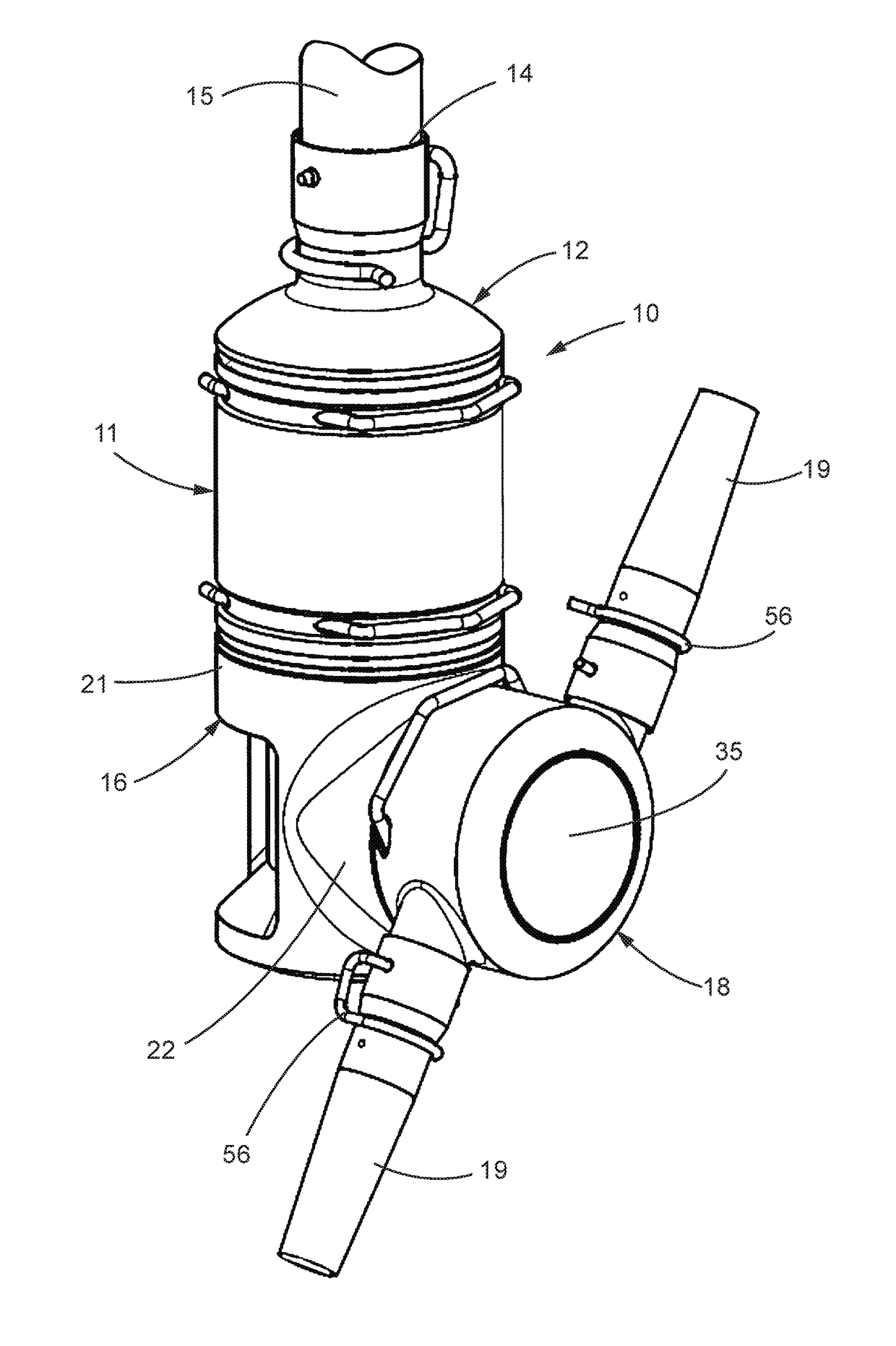
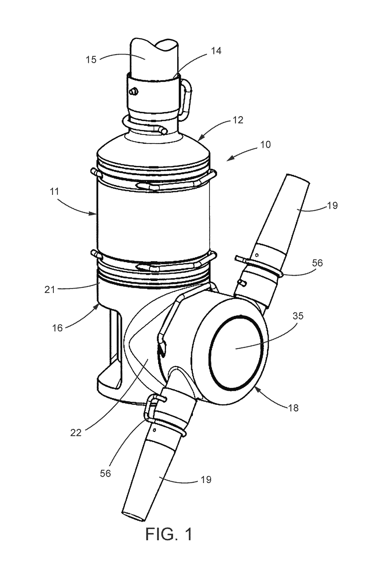
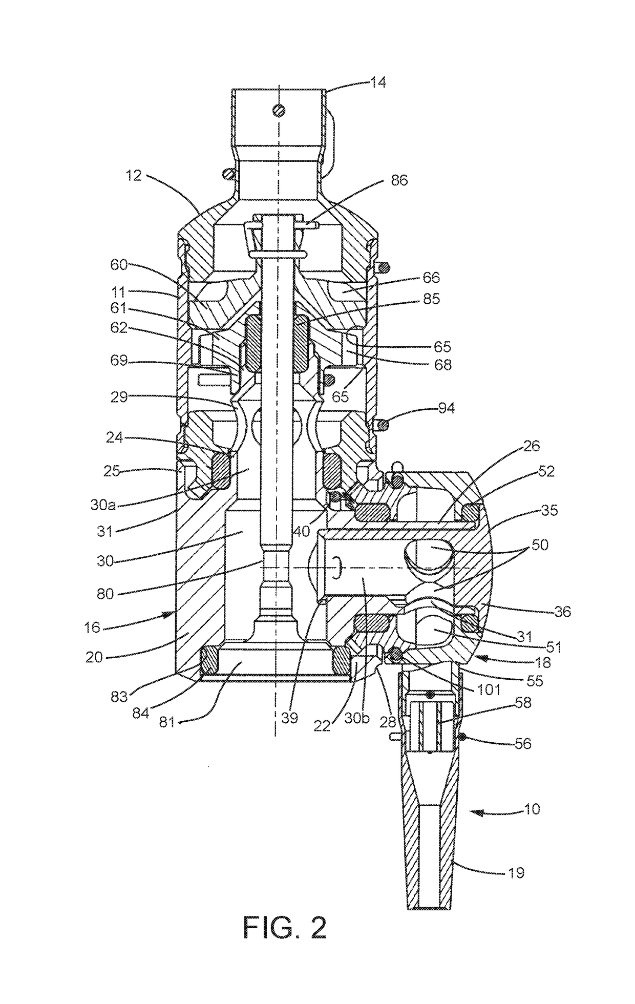
[0029]Referring now more particularly to the drawings, there is shown an illustrative rotary spray nozzle assembly 10 in accordance with the invention. The illustrated spray nozzle assembly 10 basically compromises a stationary housing 11, in this case cylindrical in shape, a liquid inlet cap 12 fixed to an upper end of the stationary housing 11 having an upper cylindrical liquid inlet 14 for coupling to a suitable cleaning liquid supply line 15, a rotary housing 16 supported at a lower end of the stationary housing 11 for relative rotation with respect to the stationary housing 11 about a central vertical axis of the stationary housing 11, and a nozzle hub 18 having a pair of oppositely directed liquid discharge nozzles 19 supported by said rotary housing 16 for relative rotation about an axis transverse to a rotary axis of the rotary housing 16.

[0030]In accordance with an important feature of the illustrated embodiment, components of the spray nozzle assembly 10 are free of thread...


PUM


Abstract

A rotary tank cleaning spray nozzle assembly which includes a stationary housing, a rotary housing for rotation about a central axis of the stationary housing, and a nozzle carrying hub supported by the rotary housing for rotation about an axis transverse to the axis of the stationary housing. A support rod extends through the rotary housing and into the stationary housing with a lower end supporting the underside of the rotary housing and the upper end being secured by a retainer. The retainer is releasable to permit removal of the rotary housing and nozzle hub from an underside of the stationary housing. A fluid driven drive for the rotary housing and nozzle hub includes a pair of removably mounted bevel gear rings. In one embodiment, liquid lubricating, frustoconical, high load carrying bearings support rotatably.

Description

CROSS-REFERENCE TO RELATED APPLICATIONS[0001]This patent application claims the benefit of U.S. Patent Application No. 62 / 250,067, filed Nov. 3, 2015, which is incorporated by reference.FIELD OF THE INVENTION[0002]The present invention relates generally to rotary cleaning devices, and more particularly, to a multi-axis rotary tank cleaning spray nozzle assembly particularly adapted for use in sanitary environments, such as processing or storage tanks in the food, dairy, and pharmaceutical industries.BACKGROUND OF THE INVENTION[0003]Rotary tank cleaning spray nozzle assemblies require complex multi-directional drives for rotating the spray nozzles in a manner that ensures the discharging spray covers all areas of the tank. Such spray nozzle assemblies require numerous parts which can be cumbersome to assemble and disassemble for sanitary cleaning as required after each usage. Threaded components of the nozzle assembly can be particularly cumbersome to assemble and disassemble, and th...

Claims


Application Information

Patent Timeline
Patent Type & Authority Patents(United States)
IPC IPC(8): B05B3/04B08B9/093
CPCB05B3/0422B08B9/0936B05B3/0445B05B15/65B05B3/04
Inventor HOFFMEYER, SCOTTNAGINEVICIUS, DIGNA
Owner SPRAYING SYST
Learn More