Apparatus comprising a spring and an optical element suspended thereon

a technology of optical elements and springs, which is applied in the field of apparatus comprising optical elements, can solve the problems of unsuitable design for optical elements having large surfaces, high space requirements, and low space efficiency of apparatus, and achieve the effects of reducing the tilting of optical elements due to a large weight of optical elements, and reducing the size of optical elements

Active Publication Date: 2018-10-09
FRAUNHOFER GESELLSCHAFT ZUR FOERDERUNG DER ANGEWANDTEN FORSCHUNG EV
View PDF17 Cites 0 Cited by
  • Summary
  • Abstract
  • Description
  • Claims
  • Application Information

AI Technical Summary

Benefits of technology

[0016]According to an embodiment, an optical element is suspended in a tiltable manner via two springs disposed between the optical element and one actuator each, wherein the springs are implemented in a straight manner and comprise a short axial expansion. Thereby, the apparatus has great space efficiency.
[0017]According to an alternative embodiment, at least one further spring is disposed on an optics-side attachment area, such that the optical element is stabilized and can be dimensioned larger.
[0018]According to a further embodiment, the optical element is disposed on actuators via four springs implemented in a straight manner, such that tilting of the optical element due to a large weight of the optical element is minimized.

Problems solved by technology

A higher space requirement is a significant disadvantage for MEMS devices.
All in all, the space efficiency of the apparatus is low.
Since an enlargement of an optical effective area of the optical elements 12′ is also accompanied by enlarged actuators 16a-d and springs 14′a-d, this design is unsuitable for optical elements having large surfaces.

Method used


Image

  • Apparatus comprising a spring and an optical element suspended thereon
  • Apparatus comprising a spring and an optical element suspended thereon
  • Apparatus comprising a spring and an optical element suspended thereon

Examples


Embodiment Construction

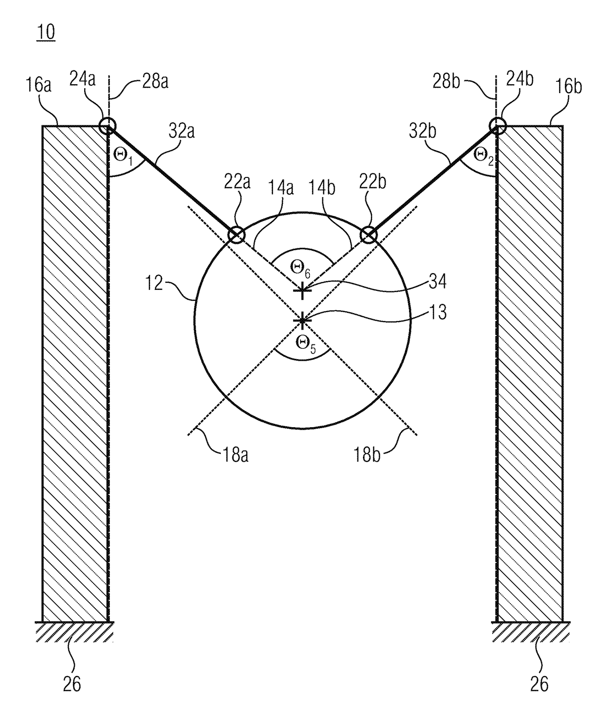
[0036]FIG. 1 shows an apparatus 10 having a round optical element 12 whose main side comprises a centroid 13 and is mounted on actuators 16a and 16b via springs 14a and 14b, tiltable around a first torsion axis 18a and a second torsion axis 18b, and the torsion axes 18a and 18b intersects at an angle θ5 adjacent to the centroid 13. The springs 14a or 14b are connected, at a first end facing the optical element 12, at an optics-side attachment area 22a or 22b, and, at a second end facing the respective actuator 16a or 16b, at actuator-side attachment areas 24a or 24b, to the optical element 12 or the actuators 16a or 16b. The optics-side attachment areas 22a and 22b comprise lateral expansions along a circumference of the main side of the optical element 12 which are each less than 10% of the circumference of the main side.

[0037]The actuators 16a and 16b are firmly cantilevered at a fixing 26 and implemented to be deflected from a resting position at the end disposed opposite to the ...


PUM


Abstract

Apparatuses with actuators having actuator-side attachment areas disposed thereon, an optical element having mirror-side attachment areas disposed thereon and springs are described, wherein an optical element is connected to actuators via two or four springs.

Description

CROSS-REFERENCE TO RELATED APPLICATIONS[0001]This application claims priority from German Patent Application No. 10 2013 210 059.0, which was filed on May 29, 2013, and is incorporated herein in its entirety by reference.BACKGROUND OF THE INVENTION[0002]The present invention relates to an apparatus comprising an optical element mounted on actuators in a tiltable manner via springs.[0003]Typically, bimorph actuators consist of an active and a passive layer, wherein the actuators use different, for example, thermal or piezoelectric expansion or contraction characteristics of the layer materials to effect deflections of the actuators.[0004]In most cases, systems comprising bimorph actuators and an optical element tiltable with large deflections around an axis in a quasi statical manner, for example a micro mirror, necessitate very large component surfaces of the systems, since the deflection of such bimorph actuators and hence the deflection of the optical element depends, among others...

Claims


Application Information

Patent Timeline
Patent Type & Authority Patents(United States)
IPC IPC(8): G02B26/08G02B26/10G02B26/12G02B7/182
CPCG02B26/08G02B26/0858G02B7/1821
Inventor GU-STOPPEL, SHANSHANKADEN, DIRKEISERMANN, CHRISTIAN
Owner FRAUNHOFER GESELLSCHAFT ZUR FOERDERUNG DER ANGEWANDTEN FORSCHUNG EV
Why Eureka
Try Eureka