
Endoscope and variable power optical system for the same

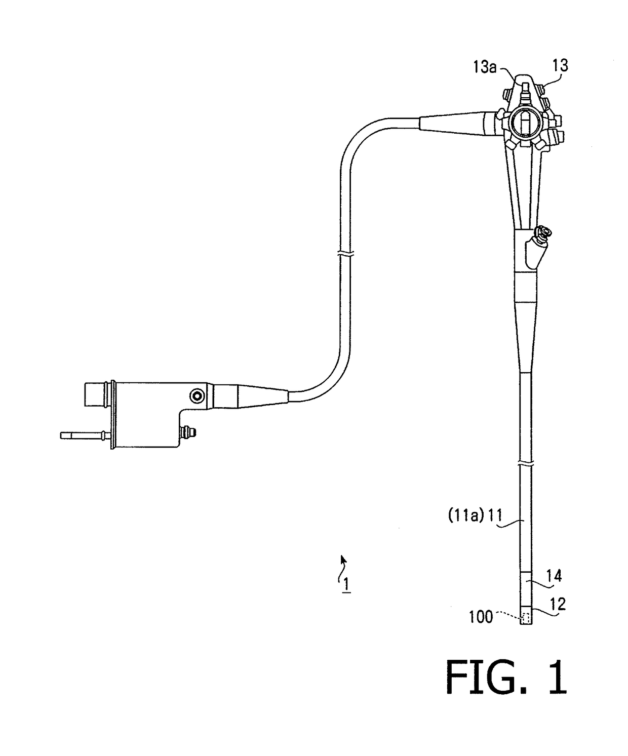
a technology of variable power and endoscope, which is applied in the field of variable power optical system of endoscope and endoscope, can solve the problems of difficult installation in the fine tip portion of the endoscope, the effect of reducing the degree of freedom regarding disposing of components, and the effective diameter of the most object side negative lens needs to be increased, so as to achieve the effect of enabling the use of electronic scopes

Active Publication Date: 2018-10-02
HOYA CORP
View PDF15 Cites 4 Cited by
  • Summary
  • Abstract
  • Description
  • Claims
  • Application Information

AI Technical Summary

Benefits of technology

The patent describes a variable power optical system for an endoscope that meets certain technical requirements to achieve the same advantageous effects as a system that satisfies different conditions. The system is designed to have a compact size and a long moving range for the second lens group, while also minimizing the observation magnification at the telephoto end to ensure good operability. The system's focus is on achieving the best optical performance while maintaining a compact size and a long moving range for the second lens group.

Problems solved by technology

However, a lens configuration of a negative-leading type (a type in which a most object side lens is a negative lens) exemplified in the patent document 1 has a drawback that the effective diameter of the most object side negative lens needs to be increased to suppress occurrence of aberrations while securing an angle of view at the wide angle end.
A variable power optical system of such a negative-leading type decreases a degree of freedom regarding disposing of components (e.g., a light guide, a forceps, an air supply or water supply channel) to be installed in a tip portion of an endoscope, and is hard to be installed in a fine tip portion of an endoscope.
Furthermore, since fluctuation of aberration becomes larger when the observing magnification is changed, it is difficult to keep the adequate optical performance over the entire region from the wide angle end to the telephoto end.

Method used


Image

  • Endoscope and variable power optical system for the same
  • Endoscope and variable power optical system for the same
  • Endoscope and variable power optical system for the same

Examples


example 1

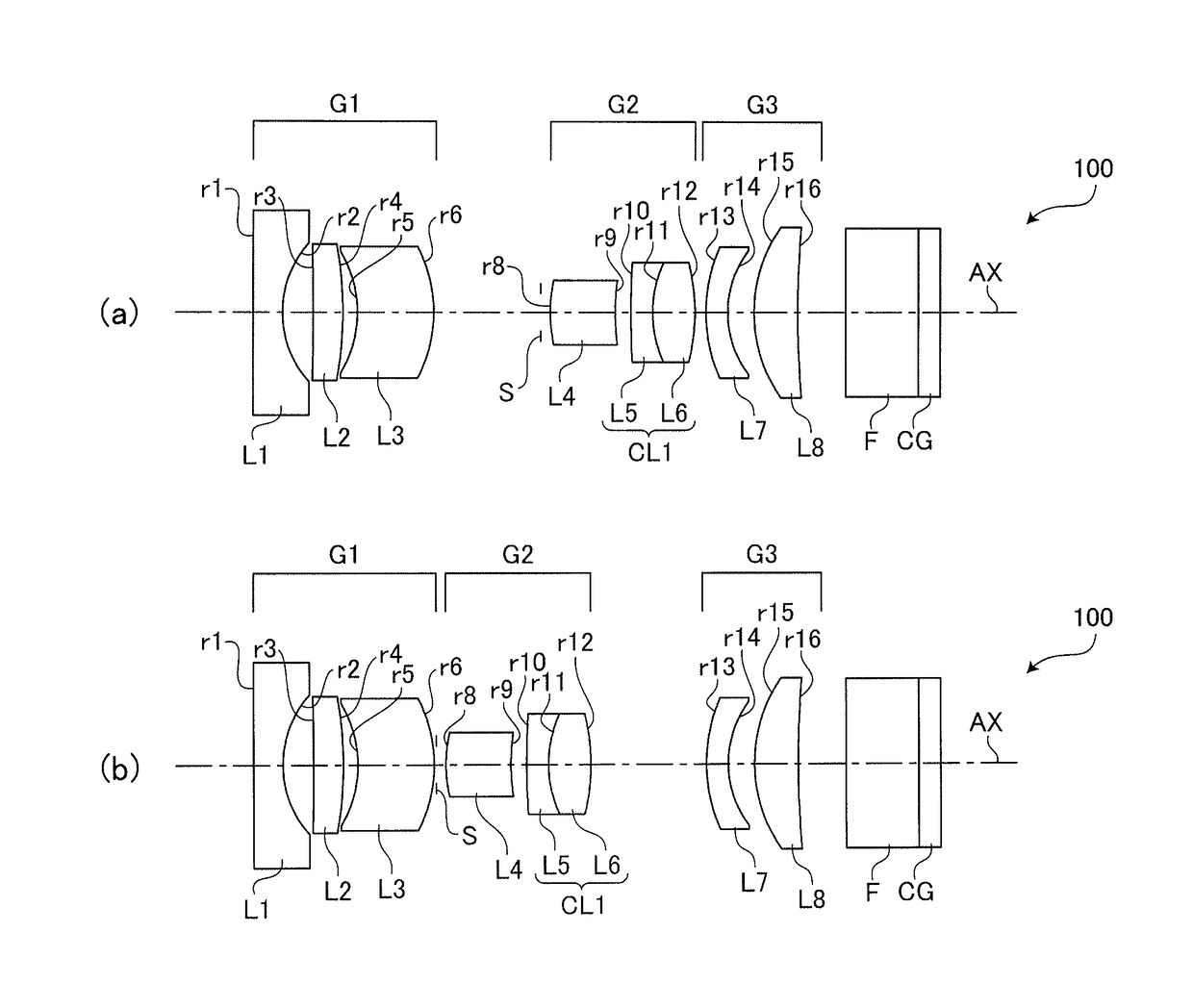
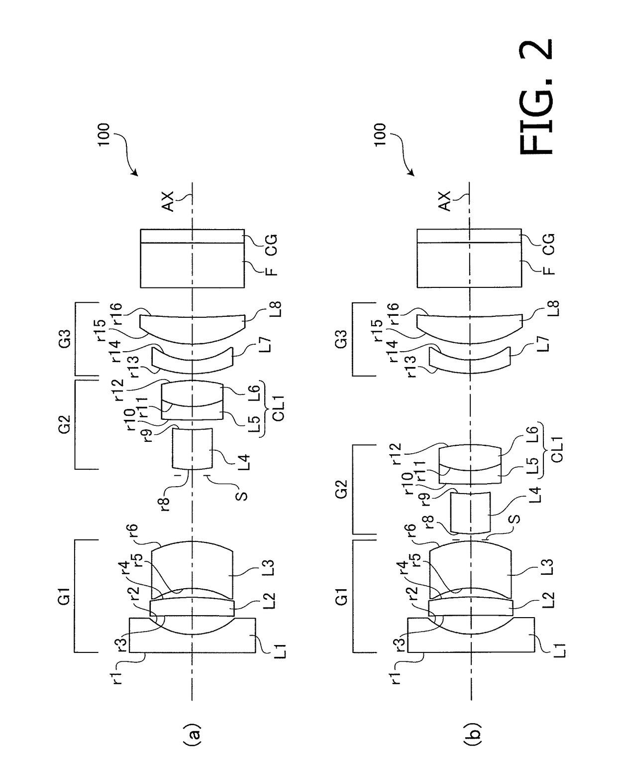
[0061]As described above, the variable power optical system 100 for an endoscope according to the example 1 has the configuration shown in FIG. 2.

[0062]Table 1 shows a concrete numerical configuration (design values) of the variable power optical system 100 for an endoscope (and the components disposed on the rear side thereof) according to the example 1. The surface number NO indicated in the top filed (surface data) in Table 1 corresponds to the surface reference rn (n: natural number) in FIG. 2, excepting the surface number 7 for the aperture stop S. In the top field of Table 1, R (unit: mm) denotes the radius of curvature of each surface of an optical component, D (unit: mm) denotes a thickness of an optical component or an interval between optical components on the optical axis, N(d) denotes a refractive index at d-line (wavelength of 588 nm), and νd denotes Abbe number at d-line.

[0063]The lower field (various data) of Table 1 shows, for each of the wide angle end and the telep...

example 2

[0067]Each of FIGS. 4(a) and 4(b) is a cross sectional view illustrating arrangement of optical components including the variable power optical system 100 for an endoscope according to the example 2. FIG. 4(a) illustrates the lens arrangement when the position of the variable power is at the wide angle end. FIG. 4(b) illustrates the lens arrangement when the position of the variable power is at the telephoto end.

[0068]Graphs A to D in FIG. 5(a) are aberration diagrams illustrating the various aberrations when the position of the variable power is at the wide angle end in the variable power optical system 100 for an endoscope according to the example 2. Graphs A to D in FIG. 5(b) are aberration diagrams illustrating the various aberrations when the position of the variable power is at the telephoto end in the variable power optical system 100 for an endoscope according to the example 2.

[0069]Table 2 shows a concrete numerical configuration and specifications of the optical components...

example 3

[0072]Each of FIGS. 6(a) and 6(b) is a cross sectional view illustrating arrangement of optical components including the variable power optical system 100 for an endoscope according to the example 3. FIG. 6(a) illustrates the lens arrangement when the position of the variable power is at the wide angle end. FIG. 6(b) illustrates the lens arrangement when the position of the variable power is at the telephoto end.

[0073]Graphs A to D in FIG. 7(a) are aberration diagrams illustrating the various aberrations when the position of the variable power is at the wide angle end in the variable power optical system 100 for an endoscope according to the example 3. Graphs A to D in FIG. 7(b) are aberration diagrams illustrating the various aberrations when the position of the variable power is at the telephoto end in the variable power optical system 100 for an endoscope according to the example 3.

[0074]Table 3 shows a concrete numerical configuration and specifications of the optical components...


PUM


Abstract

A variable power optical system for an endoscope comprising a first lens group having a negative power, a second lens group having a positive power and a third lens group, and wherein the first lens group includes at least a negative lens having a concave surface pointing to an image side and a positive meniscus lens having a concave surface pointing to an object side, the second lens group includes at least a meniscus lens having a convex surface pointing to the object side and a cemented lens formed by cementing together a negative lens and a positive lens, and the third lens group includes at least a positive lens having a convex surface pointing to the object side, and wherein the variable power optical system for an endoscope is configured to satisfy a predetermined condition.

Description

TECHNICAL FIELD[0001]The present invention relates a variable power optical system for an endoscope and an endoscope provided with such a variable power optical system.BACKGROUND ART[0002]In a medical field, an endoscope (a fiber scope or an electronic scope) is generally known as a device for observing a body cavity of a patient and has been practically used. Among endoscopes of this type, there is an endoscope provided with a variable power optical system having the variable power function for conducting fine observation for lesions.[0003]For example, Japanese Patent Publication No. JP4819969B (hereafter, referred to as a “patent document 1”) describes a concrete configuration of a variable power optical system for an endoscope. The variable power optical system for an endoscope described in the patent document 1 includes a first lens group having a negative power, a second lens group having a positive power and a third lens group having a positive power which are arranged in this...

Claims


Application Information

Patent Timeline
Patent Type & Authority Patents(United States)
IPC IPC(8): G02B23/24A61B1/00G02B15/177
CPCG02B23/2438G02B15/177A61B1/0019G02B15/14G02B15/16A61B1/00096A61B1/00186A61B1/00188A61B1/05A61B1/00163G02B15/143507G02B15/143503
Inventor NASU, SACHIKOFUJII, HIROAKI
Owner HOYA CORP
Learn More