
Speaker apparatus

a technology for speakers and speakers, applied in the direction of loudspeaker screens, transducer details, electrical transducers, etc., can solve the problem of insufficient acoustic energy (power), and achieve the effect of large acoustic energy

Active Publication Date: 2018-09-04
PANASONIC INTELLECTUAL PROPERTY MANAGEMENT CO LTD
View PDF3 Cites 0 Cited by
  • Summary
  • Abstract
  • Description
  • Claims
  • Application Information

AI Technical Summary

Benefits of technology

This configuration effectively reduces phase deviation and increases acoustic energy output, ensuring consistent and high sound pressure levels across the frequency range, particularly in line array speaker systems.

Problems solved by technology

Still further, since the outlets of the throats corresponding to the respective drivers are arranged in line in a longer axis direction at the sound hole of the waveguide, the acoustic energy (power) tends to be insufficient.

Method used


Image

  • Speaker apparatus
  • Speaker apparatus
  • Speaker apparatus

Examples


embodiment 1

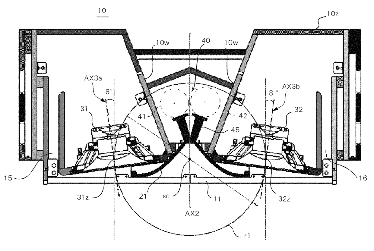
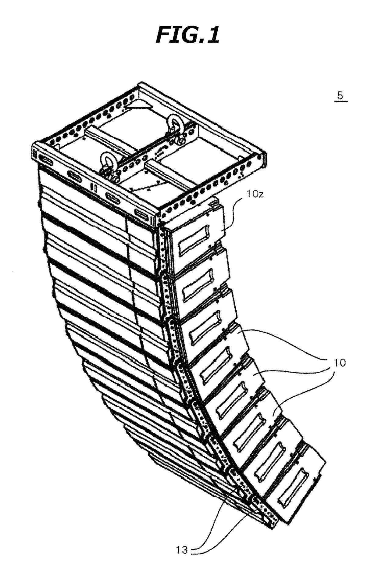
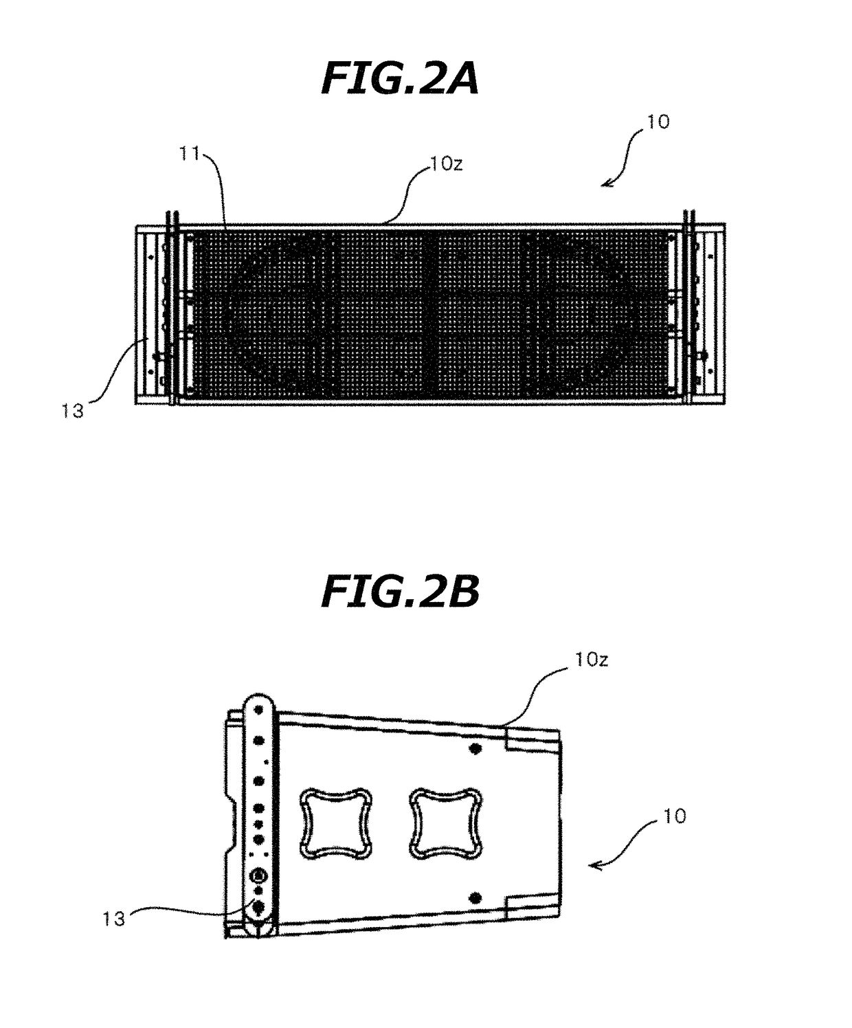
[0043]FIG. 1 shows an example appearance of a speaker array 5 according to a first embodiment. The speaker array 5 includes plural speaker modules 10 which are connected to each other to form a curved line. The top surface and the bottom surface of a case 10z of each speaker module 10 adjoins and is joined to the bottom surface of a case 10z of a speaker module 10 located above and the top surface of a case 10z of a speaker module 10 located below, respectively. The vertical range to be covered by the speaker array 5, that is, the vertical range in which acoustic signals that are output from the speaker array 5 are transmitted, is varied by changing the number of speaker modules 10 combined together to form a curved line. On the other hand, the horizontal dispersion angle of acoustic signals of the speaker array 5 is kept constant even if the number of speaker modules 10 combined together is changed.

[0044]To facilitate understanding of the description, with an assumption that the sp...

embodiment 2

[0173]The first embodiment is directed to the 3-way speaker system including the LF drivers, the MF drivers, and the HF drivers (actually, MF / HF driver units). In contrast, the second embodiment is mainly directed to a 2-way speaker system including LF drivers and an HF driver.

[0174]In describing each of speaker modules 110 according to the second embodiment, components having the same ones in each of the speaker modules 10 according to the first embodiment will be given the same reference symbols as the latter and descriptions therefor will be omitted or simplified.

[0175]FIG. 16 shows an example appearance of a speaker array 105 according to the second embodiment. The speaker array 105 includes plural speaker modules 110 which are connected to each other to form a curved line. The top surface and the bottom surface of a case 110z of each speaker module 110 adjoins and is joined to the bottom surface of a case 110z of a speaker module 110 located above and the top surface of a case ...


PUM


Abstract

A speaker apparatus includes first acoustic drivers that respectively output first acoustic signals, and an acoustic coupler having acoustic passages. The acoustic passages respectively include inlets, and an outlet of the acoustic passages is common. The first acoustic signals output from the first acoustic drivers are respectively inlet into the inlets, the first acoustic signals inlet into the inlets are guided to the common outlet, the first acoustic signals are combined at the common outlet to generate a second acoustic signal, and the second acoustic signal is output. Lengths of the acoustic passages from the inlets to the common outlet are identical to each other.

Description

CROSS-REFERENCES TO RELATED APPLICATION(S)[0001]This application is based on and claims priority from Japanese Patent Application No. 2017-019026 filed on Feb. 3, 2017, the entire contents of which are incorporated herein by reference.BACKGROUND1. Field of the Invention[0002]This disclosure relates to a speaker apparatus.2. Description of Related Art[0003]U.S. Pat. No. 6,394,223 discloses a loudspeaker that is equipped with a waveguide, plural drivers, and plural throats which are coupled acoustically to the respective drivers at their inlets and coupled acoustically to the waveguide at their outlets. In the loudspeaker, an axis of each throat forms an arc in a plane including a longer axis of the waveguide to optimize an acoustic energy distribution in the plane.[0004]In the loudspeaker, for coupling of acoustic signals at the outlet to the waveguide, the throats need to be positioned to each other accurately. Otherwise, a phase deviation tends to occur between acoustic signals tha...

Claims


Application Information

Patent Timeline
Patent Type & Authority Patents(United States)
IPC IPC(8): H04R1/02H04R1/40H04R3/14
CPCH04R1/403H04R3/14H04R1/023H04R9/02H04R9/06H04R2400/11H04R1/26H04R1/2811H04R1/2819H04R1/30
Inventor HARDESTY, GARY ALLEN
Owner PANASONIC INTELLECTUAL PROPERTY MANAGEMENT CO LTD
Learn More