
Compensation film, and optical film and display device including the same

a technology of compensating film and optical film, which is applied in the direction of instruments, polarising elements, transportation and packaging, etc., can solve the problems of deterioration of the contrast ratio, weak dependence of conventional compensation film on the viewing angle, and deterioration of the effect of other wavelengths. , to achieve the effect of strong dependence on the viewing angl

Active Publication Date: 2018-09-04
SAMSUNG ELECTRONICS CO LTD +1
View PDF30 Cites 0 Cited by
  • Summary
  • Abstract
  • Description
  • Claims
  • Application Information

AI Technical Summary

Benefits of technology

[0006]Optical properties of a conventional compensation film may be substantially dependent upon the wavelength of incident light, so such a compensation film may effectively operate for light having a certain wavelength, but the effect thereof may be deteriorated for other wavelengths. In addition, a conventional compensation film may have a strong viewing angle dependency.
[0007]An embodiment of the invention provides a compensation film with improved display characteristics by reducing the wavelength dependency and the viewing angle dependency.

Problems solved by technology

In the case of the light emitting display device, for example, an organic light emitting diode (“OLED”) display, the visibility and the contrast ratio may be deteriorated by reflection of the exterior light caused by a metal such as an electrode.
Optical properties of a conventional compensation film may be substantially dependent upon the wavelength of incident light, so such a compensation film may effectively operate for light having a certain wavelength, but the effect thereof may be deteriorated for other wavelengths.
In addition, a conventional compensation film may have a strong viewing angle dependency.

Method used


Image

  • Compensation film, and optical film and display device including the same
  • Compensation film, and optical film and display device including the same
  • Compensation film, and optical film and display device including the same

Examples


preparation example 1

Retardation Layers (Layer A to Layer D)

[0130]A poly(styrene-co-methacrylic acid) film (T080, manufactured by TOYO STYRENE) having a thickness of 100 micrometers (μm) is elongated in one axial direction (using a tension tester manufactured by Toyoseiki) at about 125° C. at a ratio of about 100% to provide a first retardation layer (A) having in-plane retardation of 220 nm at reference wavelength (550 nm).

[0131]Further, a poly(styrene-co-methacrylic acid) film (T080, manufactured by TOYO STYRENE) having a thickness of 100 μm is elongated in one axial direction (using a tension tester manufactured by Toyoseiki) at about 125° C. at a ratio of about 120% to provide a first retardation layer (B) having in-plane retardation of 240 nm at reference wavelength (550 nm).

[0132]Further, a poly(styrene-co-methacrylic acid) film (T080, manufactured by TOYO STYRENE) having a thickness of 100 μm is elongated in one axial direction (using a tension tester manufactured by Toyoseiki) at about 125° C. a...

preparation example 2

Retardation Layers (Layer E to Layer G)

[0134]A poly(styrene-co-methacrylic acid) film (T080, manufactured by TOYO STYRENE) having a thickness of 100 μm is elongated in one axial direction (using a tension tester manufactured by Toyoseiki) at about 135° C. at a ratio of about 60% to provide a second retardation layer (E) having in-plane retardation of 100 nm at reference wavelength (550 nm).

[0135]Further, a poly(styrene-co-methacrylic acid) film (T080, manufactured by TOYO STYRENE) having a thickness of 100 μm is elongated in one axial direction (using a tension tester manufactured by Toyoseiki) at about 135° C. at a ratio of about 75% to provide a second retardation layer (F) having in-plane retardation of 120 nm at reference wavelength (550 nm).

[0136]Further, a poly(styrene-co-methacrylic acid) film (T080, manufactured by TOYO STYRENE) having a thickness of 100 μm is elongated in one axial direction (using a tension tester manufactured by Toyoseiki) at about 135° C. at a ratio of a...

examples 1 to 8

f Compensation Films

[0137]The first retardation layers (A-D) according to Preparation Example 1 and the second retardation layers (E-G) according to Preparation Example 2 are assembled as described in Table 1 below to provide compensation films according to Examples 1 to 8.

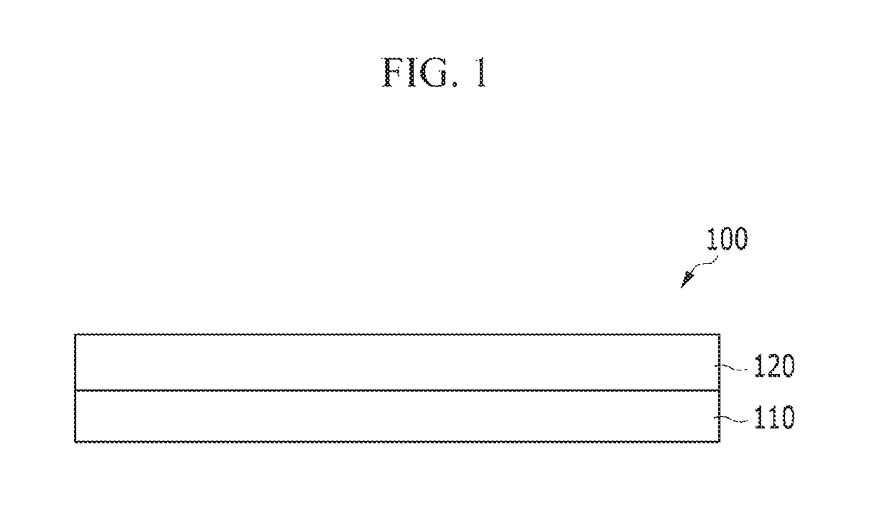
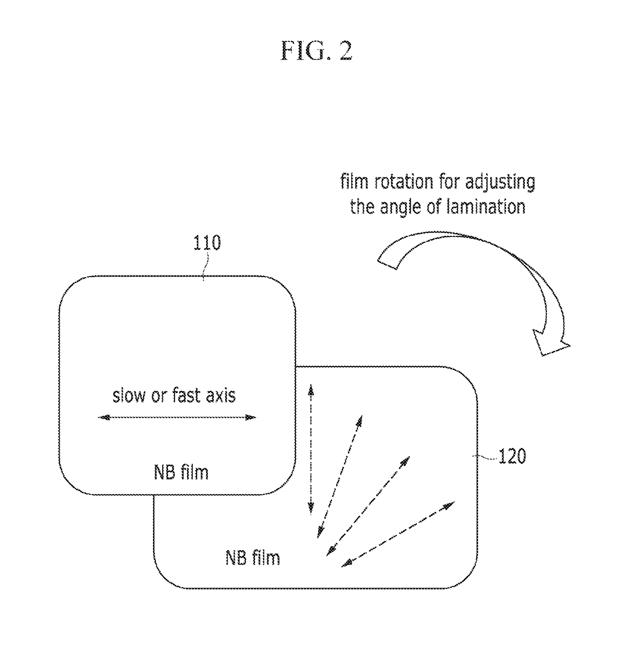
[0138]Particularly, a first retardation layer and a second retardation layer are assembled in pairs as described in Table 1 by disposing the second retardation layer below the first retardation layer to have a specific angle between the slow axes or the fast axes thereof from 0° to 90°. Subsequently, an adhesion film is transcribed on one side of either the first retardation layer or the second retardation layer, and then the releasing film attached to the other side of the adhesion film is removed to provide a compensation film assembled with the first retardation layer and the second retardation layer maintaining the specific angle between the slow axes or the fast axes thereof. The assembly of the layers is pro...


PUM

PropertyMeasurementUnit
wavelengthsaaaaaaaaaa
angleaaaaaaaaaa

Abstract

A compensation film includes a first retardation layer comprising a polymer having negative birefringence, and a second retardation layer comprising a polymer having negative birefringence, where the first retardation layer has an in-plane retardation (Re1) in a range of about 180 nanometers to about 300 nanometers for incident light having a wavelength of about 550 nanometers, the second retardation layer has an in-plane retardation (Re2) in a range of about 60 nanometers to about 170 nanometers for the incident light having the wavelength of about 550 nanometers, and the entire in-plane retardation (Re0) of the first retardation layer and the second retardation layer for incident light having wavelengths of about 450 nanometers and about 550 nanometers satisfies the following inequation: Re0 (450 nm)<Re0 (550 nm).

Description

CROSS-REFERENCE TO RELATED APPLICATION[0001]This application claims priority to Korean Patent Application No. 10-2014-0169674 filed on Dec. 1, 2014, and all the benefits accruing therefrom under 35 U.S.C. § 119, the content of which in its entirety is herein incorporated by reference.BACKGROUND1. Field[0002]Embodiments of the invention relate to a compensation film, an optical film including the compensation film, and a display device including the compensation film or the optical film.2. Description of the Related Art[0003]A flat panel displays may be classified into a light-emitting display device that emits light by itself and a non-emissive display device that includes a separate light source, and a compensation film such as a retardation film is generally employed for improving the image quality thereof.[0004]In the case of the light emitting display device, for example, an organic light emitting diode (“OLED”) display, the visibility and the contrast ratio may be deteriorated ...

Claims


Application Information

Patent Timeline
Patent Type & Authority Patents(United States)
IPC IPC(8): G02B5/30H01L51/52G02F1/13363
CPCG02B5/3083G02F1/133634H01L51/5275H01L51/5281Y10T428/1036G02F2001/133637G02F2001/133638Y10T428/10C09K2323/03C09K2323/00G02F1/133637G02F1/133638H10K59/8791H10K59/879G02B5/30G02B5/3008G02F1/1335H10K50/86H10K50/858
Inventor KIM, HYUNG JUNLEE, JI-HOONKONG, HYE YOUNGWON, JONG HOONJUNG, MYUNG SUP
Owner SAMSUNG ELECTRONICS CO LTD
Learn More