
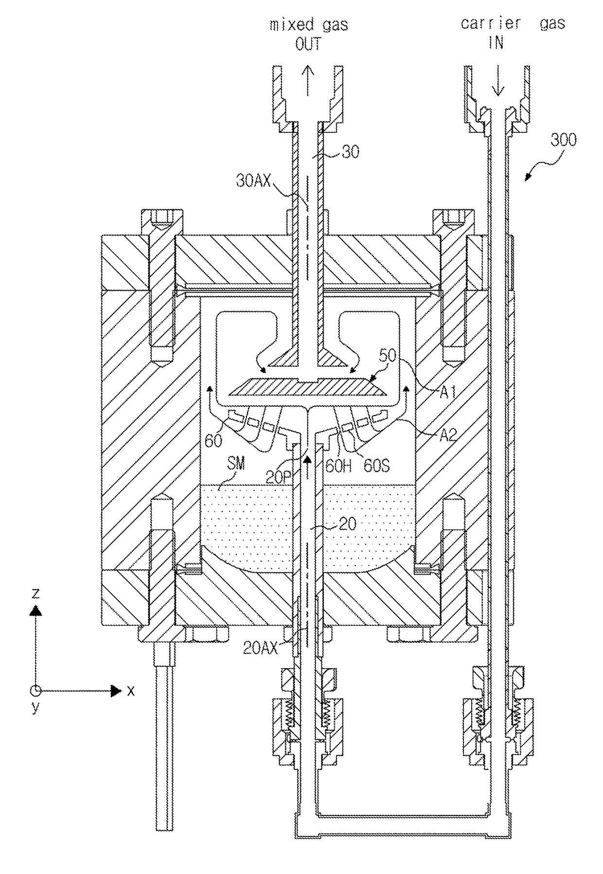
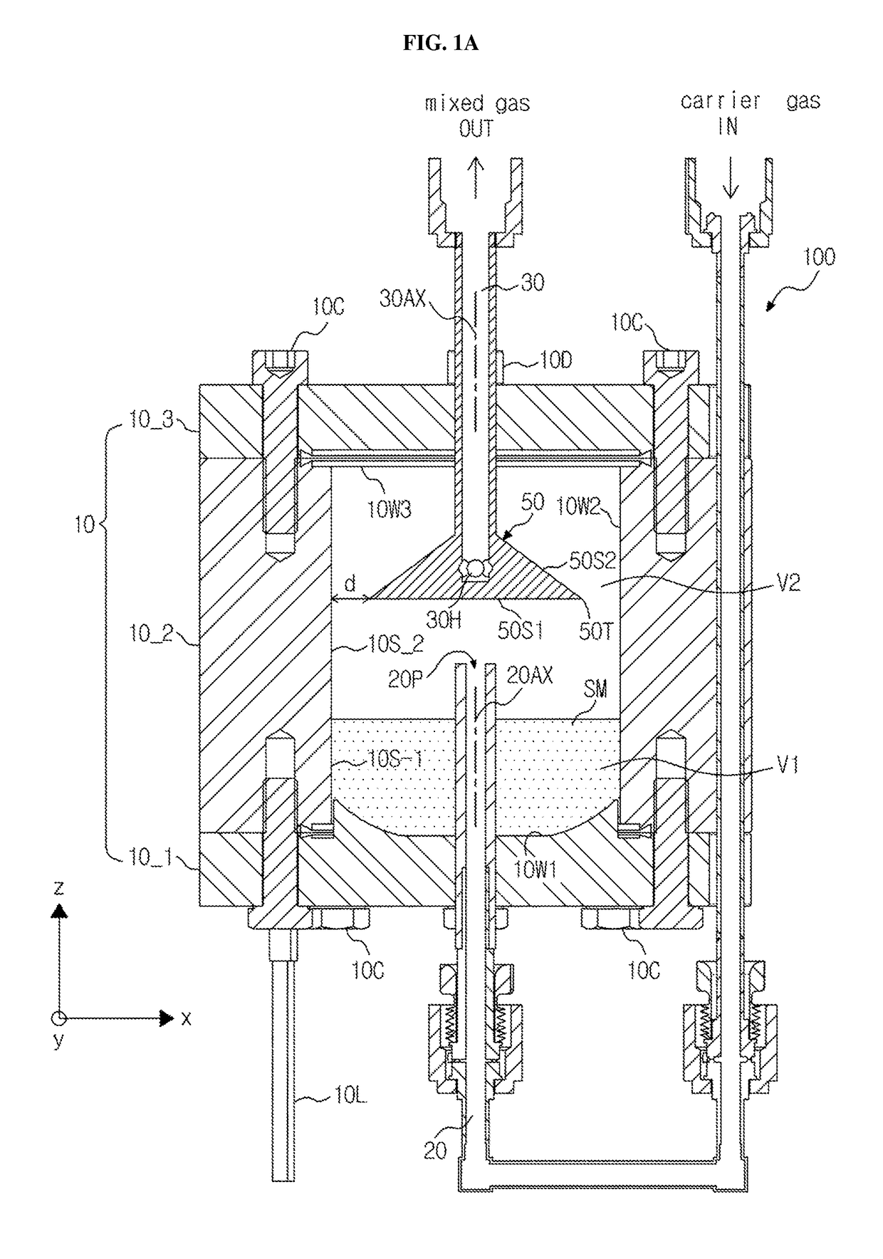
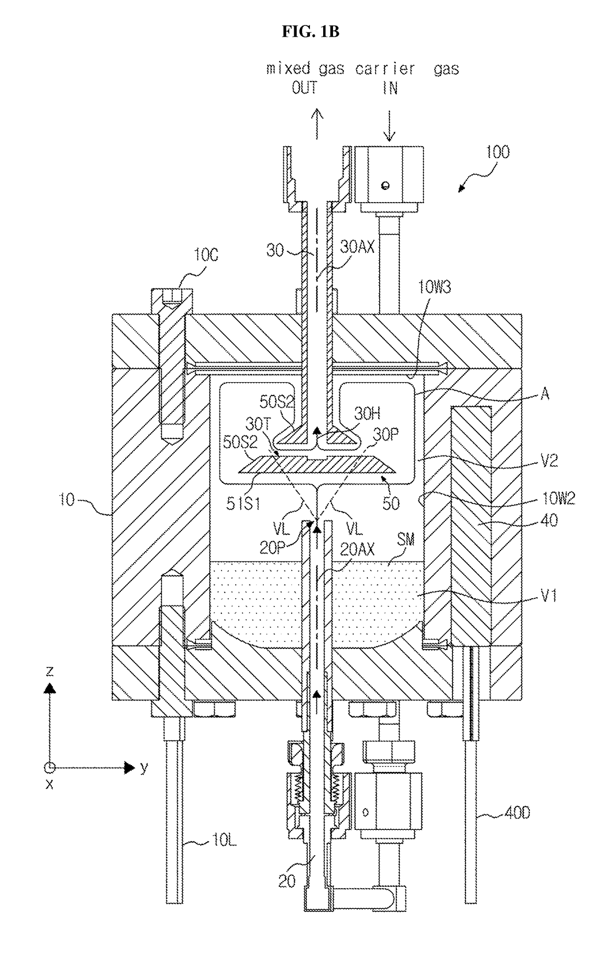
Source container and vapour-deposition reactor

a source container and vapour deposition technology, applied in the direction of vacuum evaporation coating, transportation and packaging, coatings, etc., can solve the problems of non-uniform amount of carried vapour precursor or precipitation of the same, and achieve the effect of improving temperature consistency inside the container, reducing cold spots in the container, and maintaining constant amount of carried vapour precursor

Active Publication Date: 2018-09-04
UNITEX
View PDF43 Cites 1 Cited by
  • Summary
  • Abstract
  • Description
  • Claims
  • Application Information

AI Technical Summary

Benefits of technology

The present invention provides a device for improving the mixing of carrier gas and vapor from a source material during a chemical reaction. The device has a first space and a second space, with flow barrier surfaces between them. This design creates a longer distance for the gas flow, allowing carrier gas to better mix with the vapor. Hot carrier gas flows in a smooth manner along the first flow barrier surface, resulting in improved temperature consistency and reduction of cold spots. The particles formed due to cold spots are absorbed or reflected by the flow barrier surfaces, preventing them from causing defects in the finished device. This design also prevents introduction of particles to the discharging port, improving the quality of the finished device.

Problems solved by technology

However, due to heat sensitivity as well as low vapour pressure, vapour-deposition using a solid phase source exhibits various technical problems, such as non-uniformity in amount of carried vapour precursor or precipitation of the same.

Method used


Image

  • Source container and vapour-deposition reactor
  • Source container and vapour-deposition reactor
  • Source container and vapour-deposition reactor

Examples


Embodiment Construction

[0024]The present invention will now be described more fully with reference to the accompanying drawings, in which exemplary embodiments of the invention are shown.

[0025]The invention may, however, be embodied in many different forms and should not be construed as being limited to the embodiments set forth herein; rather these embodiments are provided so that this disclosure will be thorough and complete, and will fully convey the concept of the invention to one of ordinary skill in the art. Meanwhile, the terminology used herein is for the purpose of describing particular embodiments only and is not intended to be limiting of exemplary embodiments.

[0026]Also, thickness or sizes of layers in the drawings are exaggerated for convenience of explanation and clarity, and the same reference numerals denote the same elements in the drawings. As used herein, the term “and / or” includes any and all combinations of one or more of the associated listed items.

[0027]The terminology used herein i...


PUM

PropertyMeasurementUnit
angleaaaaaaaaaa
temperatureaaaaaaaaaa
vapour pressureaaaaaaaaaa

Abstract

The present invention relates to a source container and to a vapor-deposition reactor. The source container according to one embodiment of the present invention comprises: a container comprising an inner wall for delimiting a first space for holing a source material, and a second space which is adjacent to the first space and is for the mixing of vapor emitted from the source material and a carrier gas taken into the inside thereof; a carrier gas inflow pathway which connects the outside of the container second space; a mixed gas discharge pathway which connects the outside of the container and the second space; and a flow-limiting member which expands inside the second space, and provides a first flow barrier surface between the inflow port and the discharge port.

Description

[0001]This application claims the priority of Korean Patent Application No. 10-2012-0031891, filed on Mar. 28, 2012 in the KIPO (Korean Intellectual Property Office), the disclosure of which is incorporated herein entirely by reference. Further, this application is the National Stage application of International Application No. PCT / KR2013 / 002496, filed Mar. 26, 2013, which designates the United States and was published in Korean. Each of these applications is hereby incorporated by reference in their entirety into the present application.TECHNICAL FIELD[0002]The present invention relates to a vapour-deposition technique, and more particularly, a source container for generating a vapour precursor and a vapour-deposition reactor including the same.BACKGROUND ART[0003]In a semiconductor fabricating apparatus or a display manufacturing apparatus, a reactor for forming a thin-film via a vapour deposition method, such as a chemical vapour deposition (CVD), an atomic layer deposition (ALD)...

Claims


Application Information

Patent Timeline
Patent Type & Authority Patents(United States)
IPC IPC(8): B01F3/02B01F5/00C23C14/22C23C14/24C23C16/44C23C16/448C23C16/455B01F23/10
CPCC23C16/45512B01F3/02B01F5/00C23C16/45502C23C14/243C23C16/4402C23C16/4481C23C14/228B01F23/10B01F25/00C23C16/448C23C16/44
Inventor LEE, MYUNG GILEE, YONG EUIKIM, UN JUNG
Owner UNITEX
Learn More