Brushless DC motor incorporating single pole double throw magnetic switch

a brushless dc motor and switch technology, applied in the direction of dynamo-electric converter control, magnetic circuit rotating parts, magnetic circuit shape/form/construction, etc., can solve the problems of increasing the cost of these motors, reducing the total efficiency of such motors, and complicated manufacturing, and achieve simple construction and high efficiency.

Inactive Publication Date: 2018-08-21
POZMANTIR MICHAEL +1
View PDF25 Cites 2 Cited by
  • Summary
  • Abstract
  • Description
  • Claims
  • Application Information

AI Technical Summary

Benefits of technology

[0007]The present invention overcomes the aforementioned disadvantages by providing a highly efficient, reliable, simply constructed, and inexpensive brushless DC motor incorporating only one single pole double throw hermetic magnetic switch.

Problems solved by technology

While Hall Effect sensors are reliable and widely used in brushless motors, they have some disadvantages.
They require additional electronic components, which complicates manufacturing and increases the cost of these motors.
Also, additional circuitry and Hall generators themselves consume some electrical energy therefore decreasing the total efficiency of such motors, particularly noticeable in small electric motors working on low electric currents.
The electrical contacts in this motor are exposed, which affects its life time and reliability.
Additional magnets or shielding disks are needed to control reed switch activation which makes these motors mechanically complex.
Brushless motors incorporating reed switches are not widely used in the industry because of the common misconception of their lower reliability as compared to semiconductor sensors that have no mechanical parts.
Simple replacement of the Hall Effect sensor with a reed switch in any type of known brushless motor presents technical difficulties and is not obvious for any person with ordinary skills in the art.

Method used


Image

  • Brushless DC motor incorporating single pole double throw magnetic switch
  • Brushless DC motor incorporating single pole double throw magnetic switch
  • Brushless DC motor incorporating single pole double throw magnetic switch

Examples


Embodiment Construction

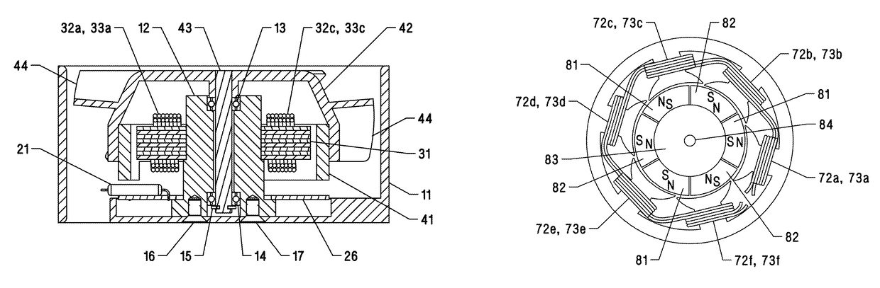
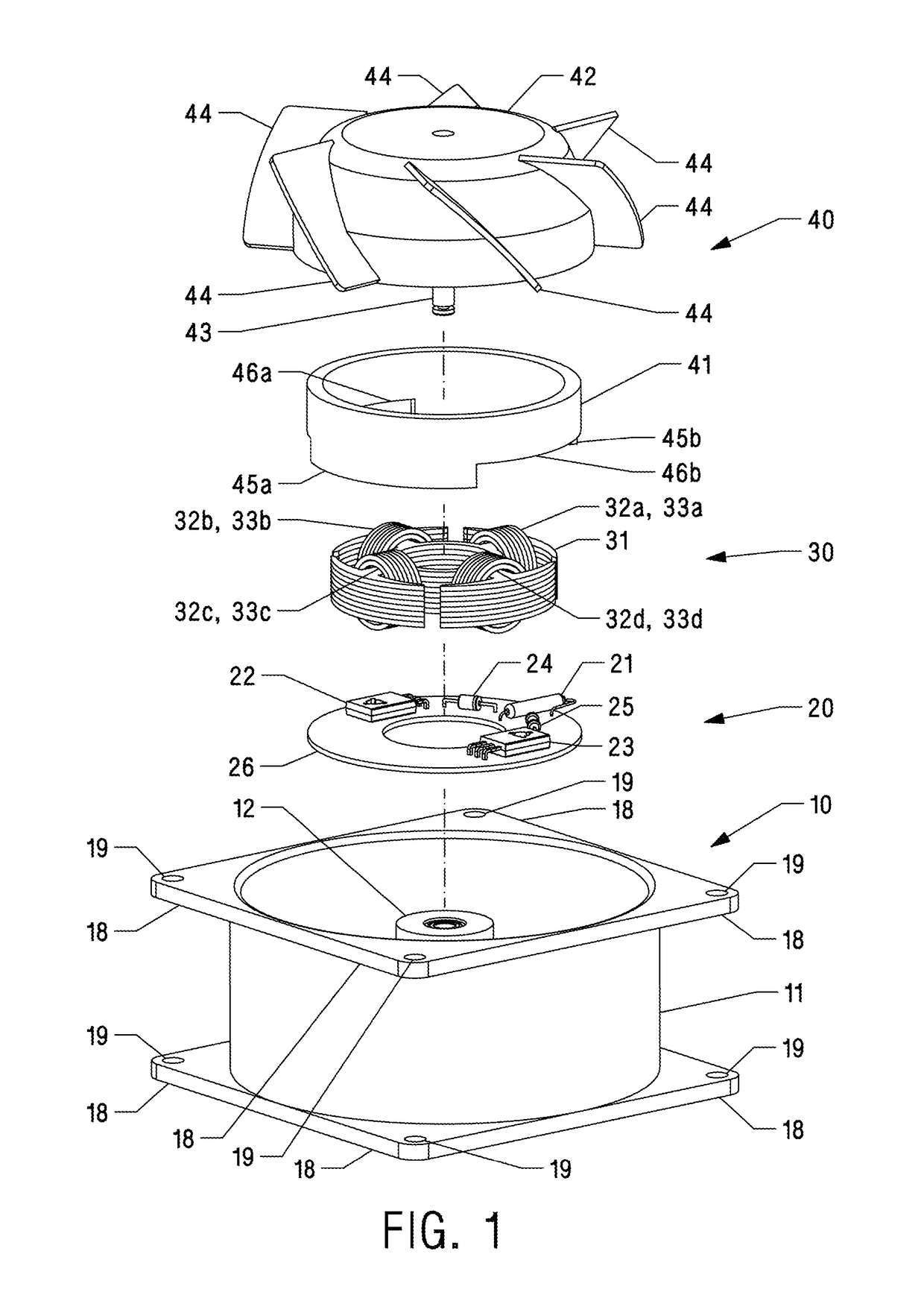
[0020]One embodiment of the motor is illustrated in FIG. 1 (three-dimensional exploded view showing main components) and FIG. 2 (cross-sectional view taken along the axis of the motor shaft). The motor consists of a casing assembly 10, a stator 30, a permanent magnet rotor 40, and a printed circuit board (PCB) 20 containing electronic control components.

[0021]A casing 11 is generally adapted to a hollow cylindrical configuration having four extending corner flanges 18 with mounting holes 19 on inlet and outlet sides. It can be manufactured from die-cast aluminum or plastic but other suitable materials could be used. A housing 12 is secured to the casing 11 by means of screws 16 and 17. The stator 30 consists of a plurality of stacked laminations 31 forming four identical poles of a customary T-shape, that are essentially umbrella or mushroom shaped, each pole extending circumferentially over an extended arc or sector, covering almost an entire quarter of a circle with narrow gaps be...


PUM


Abstract

A brushless DC motor utilizing a single pole double throw reed switch as a rotor position sensor. In one embodiment, the motor has a four-pole internal stator with bifilar windings providing alternating polarization for each subsequent pole, and a hollow outer rotor with radially magnetized ring-shaped permanent magnet. The rotor magnet has magnetically uninterrupted four-pole torque generating surface and incorporates features to interact with the reed switch. A non-uniform air gap between the stator poles and an inner surface of the rotor magnet allows generating a complementary reluctance torque between the energization pulses. The motor includes means to limit the electric current through the reed switch.

Description

BACKGROUND—PRIOR ART[0001]The present invention relates to pulse brushless direct current electric motors.[0002]Brushless DC motors are widely used because they are stable, reliable, efficient, and require little or no maintenance. A typical brushless motor consists of a stator structure having a plurality of electromagnets, a permanent magnet rotor, and a sensor which controls the energization of the torque-creating stator electromagnets in pulses depending on the position of the rotor. Several types of brushless motors comprising this structure have been proposed—for example, in U.S. Pat. No. 3,873,987 (1975), U.S. Pat. No. 4,374,347 (1983), and U.S. Pat. No. 4,547,714 (1985), all to Muller, U.S. Pat. No. 4,030,005 to Doemen (1977), and U.S. Pat. No. 5,095,238 to Suzuki et al. (1992). All of these motors use semiconductor sensing elements based on the Hall Effect. While Hall Effect sensors are reliable and widely used in brushless motors, they have some disadvantages. They require...

Claims


Application Information

Patent Timeline
Patent Type & Authority Patents(United States)
IPC IPC(8): H02K11/215H02P1/00H02K21/16H02K21/22H02K1/02H02K1/14H02K1/27H02K3/28H02K7/14H02K11/33F04D19/00F04D25/06F04D25/08
CPCH02K11/215F04D25/068F04D25/0646F04D25/08H02K1/02H02K1/146H02K1/2706H02K1/2786H02K3/28H02K7/14H02K11/33H02K21/16H02K21/222H02P1/00F04D19/002H02K2201/03H02K1/2791
Inventor POZMANTIR, MICHAELPOZMANTIR, SERGEY
Owner POZMANTIR MICHAEL
Why Eureka
Try Eureka