
Active lightning conductor

a technology of active lightning and conductors, applied in the direction of discharge by conduction/dissipation, active discharge triggering, electrical devices, etc., can solve the problems of low security of objects against destruction, inconvenient device, high complexity of execution, etc., to improve the reliability and service life of the device, improve the structural, technological and operational performance of the lightning conductor, and improve the protection of facilities against damage

Inactive Publication Date: 2018-08-21
MATVEEV VALERY MIKHAILOVICH +2
View PDF14 Cites 0 Cited by
  • Summary
  • Abstract
  • Description
  • Claims
  • Application Information

AI Technical Summary

Benefits of technology

[0010]The aim of the present invention is to improve the structural, technological and operational performance of the lightning conductor, to improve the reliability and the service life of the device and to provide a better protection of facilities against damages by lightning discharges.
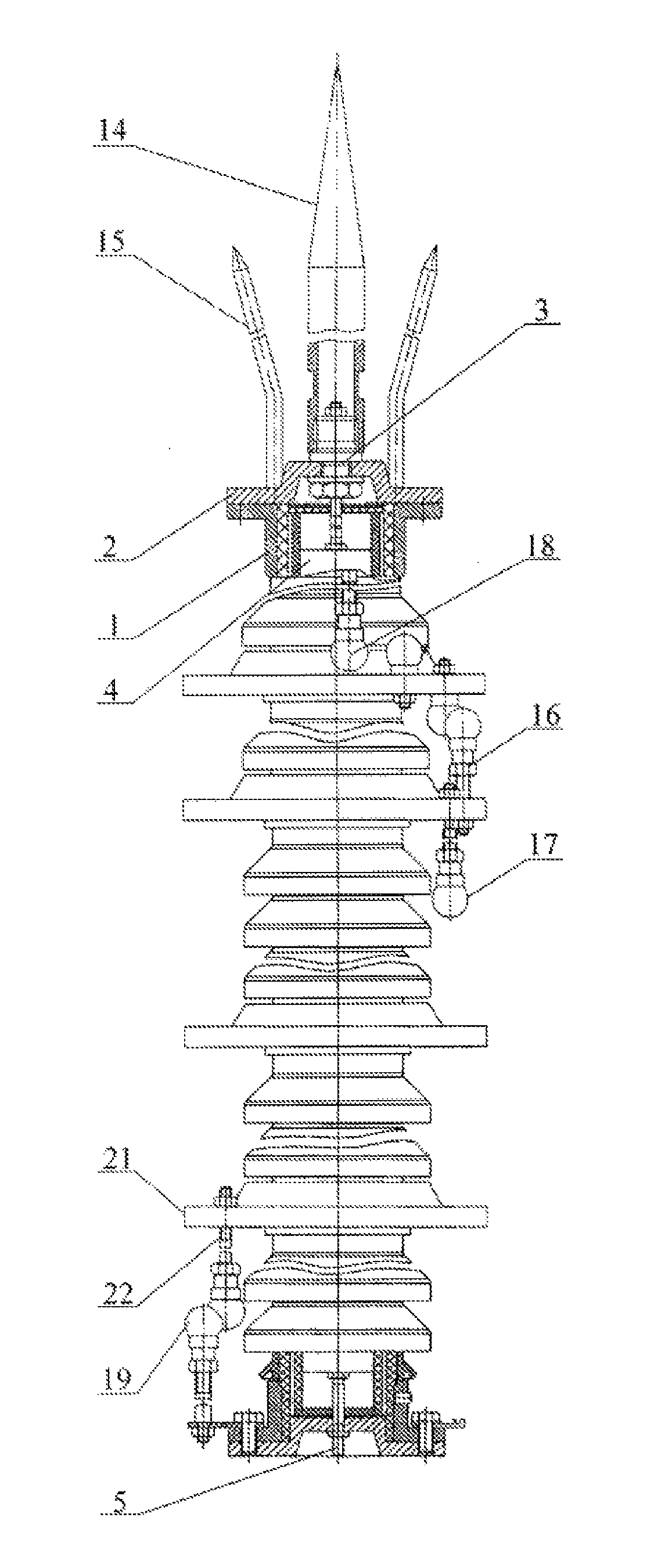
[0035]The technical result provided with the disclosed combination of features resides in the improvement of structural, technological and operating performance of the lightning conductor, in the improvement of the device operation reliability and in the provision of improved protection of facilities against damages due to lightning discharge thanks to a more reliable structural design of arresters, to the mutual arrangement and to the combination of a capacitor discharge circuit and of charging resistor circuits. The external discharge circuit serves to protect the impulse voltage generator against the effect of electric current. At the moment of a lightning hit on the lightning conductor, all the charge runs out by the external arresters, thereby impeding the destructive effect of the lightning on the internal generator, which improves the operational reliability of the lightning conductor and the protection of facilities of various kind in the case of an intensive attack of atmospheric electricity.

Problems solved by technology

Shortcomings of this known device reside in a high complexity of execution and in a low security of the objects against destruction by lightning.
An inconvenient of this device resides in the need to select electromagnetic parameters for its operation while a lightning leader of a determined type approaches the object to be protected.
Such protection is not secure enough.
An inconvenient of this known lightning conductor resides in a very low service life and in insufficient reliability of the same due to its construction.
A shortcoming of this known solution is insufficient reliability and insufficient service life of the device.

Method used


Image

  • Active lightning conductor
  • Active lightning conductor
  • Active lightning conductor

Examples


Embodiment Construction

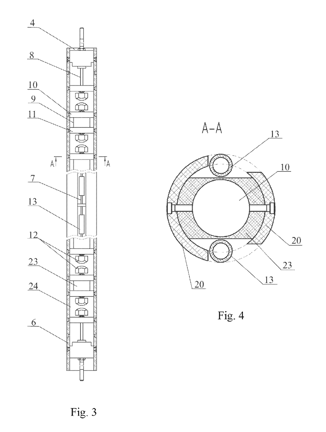
[0041]The active lightning conductor comprises a housing 1 with a cover 2, an active lightning-receiving unit 3 connected in series to a high-voltage impulse generator 4 excited by an external lightning-induced magnetic field, and to a contact element 5 of the grounding system.

[0042]The generator 4 presents a case 6 the outer side of which encloses at least two charging resistor circuits 7 as well as a multiunit arrester made as at least one capacitive discharge circuit 8 composed of in-line alternating capacitors 9. Each capacitor 9 has two charging plates 10, 11, and arresters 12 functionally combined with the same and made as projections of adjusted height on the outer side of said plates 10, 11. The charging resistor circuits 7 are composed of resistors 13 connected in series and divided into two groups. The resistors of one of them are connected to the upper capacitor plates 10 and the resistors of the other group are connected to the lower capacitor plates 11 of the capacitors...


PUM


Abstract

The present invention relates to means for protecting various purpose facilities against damages when they are exposed to an intensive action of atmospheric electricity, in particular to means for protecting buildings and structures against lightning. The active lightning conductor comprises a housing with a cover, an active lightning-receiving unit connected in series to a high-voltage impulse generator excited by an external lightning-induced magnetic field, and to a contact element of a grounding system. The generator comprises at least two charging resistor circuits as well as a multiunit arrester made as at least one capacitive discharge circuit composed of in-line alternating capacitors each of them having two charging plates with arresters. The charging circuit resistors are divided into two groups the resistors of one of them being connected to the upper capacitor plates and the resistors of the second group being connected to the lower capacitor plates. The electromagnetic parameters of the lightning conductor provide for a possibility to charge the capacitors from an external electric field at a critical active lightning voltage of the last until a level sufficient to form and to execute a preventive discharge providing for the formation of a leader sent via the lightning-receiving unit to meet the striking leader from an external lightning, but in this case said capacitor electric capacitance and said ohmic resistance of the interlayers between the capacitor plates and the arrester protrusions are adopted with values providing for the possibility of a reach-through breakdown of the arresters in this circuit and the possibility of a short-circuit of the lightning-receiving unit with the contact element of the grounding system at a lightning discharge. The lightning-receiving unit is made as a multirod rim with a central rod and side rods. The lightning conductor is provided with an external discharge circuit composed of couples of current-carrying arresters. Each arrester of one couple is electrically coupled to one arrester of another couple. One arrester of the upper couple is electrically linked to the lightning-receiving unit, and one arrester of the lower couple is linked to the contact element of the grounding system. The arresters of adjacent couples are located on the housing with a partial shift in the plan view relative to the previous and / or following couple of arresters.The technical result resides in the improvement of structural, technological and operating performance of the lightning conductor, in the improvement of the device operation reliability and in the provision of improved protection of facilities against damages due to lightning discharge hits.

Description

RELATED APPLICATION[0001]This application claims the benefit of PCT / RU2012 / 000658, which claims priority from RU 2011152210 filed Dec. 21, 2011.FIELD OF THE INVENTION[0002]The present invention relates to a means protecting various-purposed objects against damages when they are exposed to an intensive action of atmospheric electricity, in particular to a means for protecting against lightning striking industrial buildings and structures as well as electric power equipment located outdoors.BACKGROUND OF THE INVENTION[0003]A conventional lightning conductor comprises a central vertical grounded rod with some lateral lightning-receiving antennas located symmetrically thereto in combination with a generating electrode, some arresters, a converter of electric field energy, and energy storage units. An arrester is placed in a gap between the central grounded rod and the generating electrode. Similar arresters are located in the gaps of the lateral lightning-receiving antennas. The first i...

Claims


Application Information

Patent Timeline
Patent Type & Authority Patents(United States)
IPC IPC(8): H02G13/00
CPCH02G13/00H02G13/80H02G13/20
Inventor MATVEEV, VALERY MIKHAILOVICHNASONOV, SERGEI VALENTINOVICHPISAREVSKY, YURY VALENTINOVICH
Owner MATVEEV VALERY MIKHAILOVICH
Learn More