Fuel property sensor
a technology of property sensor and fuel, which is applied in the direction of liquid fuel feeder, machines/engines, instruments, etc., can solve the problems of low versatility, impurities contained in fuel, and the sensor of patent document 1 cannot detect a substance that is hardly soluble in water, so as to achieve the effect of simple and more versatile fuel property sensor
- Summary
- Abstract
- Description
- Claims
- Application Information
AI Technical Summary
Benefits of technology
Problems solved by technology
Method used
Image
Examples
embodiments
First Embodiment
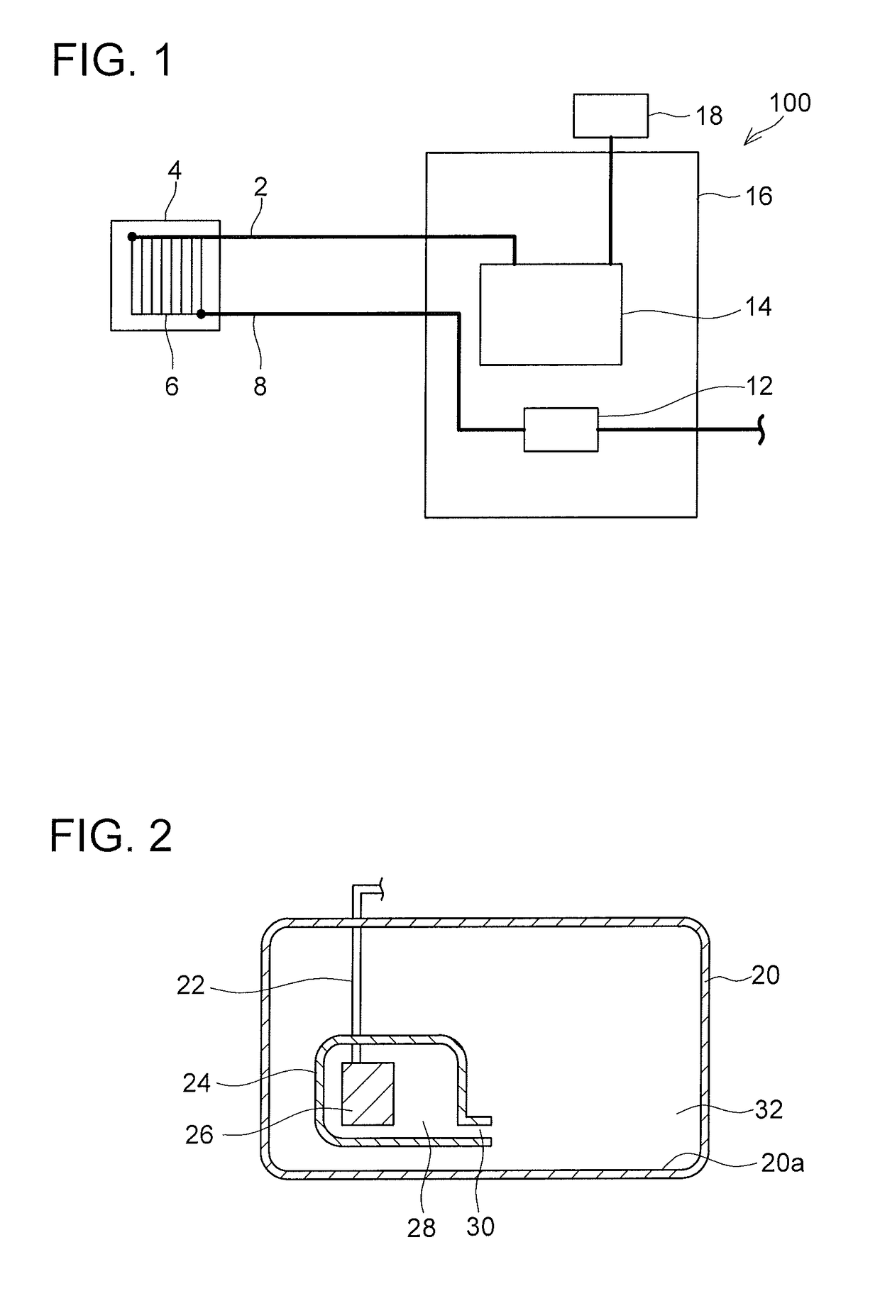
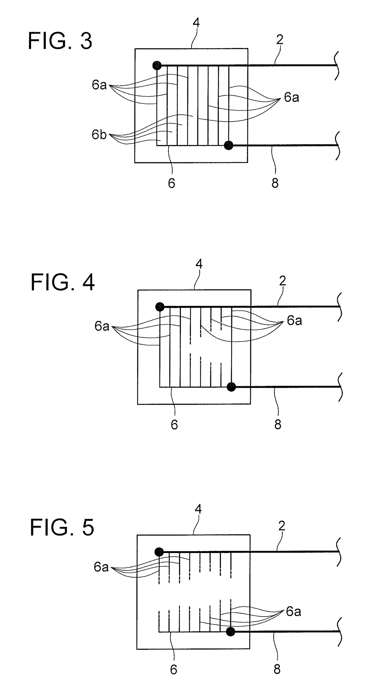
[0044]As shown in FIG. 1, a fuel property sensor 100 includes a substrate 4, a first lead wire 2, a second lead wire 8, and a determiner 16. The substrate 4 is disposed in such a position as to be in contact with fuel used in an engine (not illustrated). The first lead wire 2 and the second lead wire 8 are connected to the substrate 4. The first lead wire 2 and the second lead wire 8 are spaced from each other. A wiring member 6 is provided on a front surface of the substrate 4. The wiring member 6 connects the first lead wire 2 and the second lead wire 8. The wiring member 6 has electrical conductivity. Therefore, the first lead wire 2 and the second lead wire 8 are electrically connected to each other. The wiring member 6 will be described in detail later.
[0045]The determiner 16 includes a signal outputting unit 14 and a signal receiving unit 12. A power supply 18 is connected to the signal outputting unit 14. The signal outputting unit 14 is configured to supply a...
second embodiment
[0059]A fuel property sensor 200 is described with reference to FIG. 15. The fuel property sensor 200 is a modification of the fuel property sensor 100. The fuel property sensor 200 differs from the fuel property sensor 100 in that a signal outputting unit 14 of the fuel property sensor 200 outputs signals to a plurality of lead wires. Components of the fuel property sensor 200 which are substantially identical to those of the fuel property sensor 100 are given the same reference numerals as those of the fuel property sensor 100, and as such, may not be described below.
[0060]In the fuel property sensor 200, the signal output unit 14 outputs signals to the first lead wire 2 and a third lead wire 50. As will be described in detail later, a signal that is outputted to the first lead wire 2 and a signal that is outputted to the third lead wire 50 are different from each other. The third lead wire 50 is connected to the second lead wire 8. Therefore, the signal receiving unit 12 receives...
third embodiment
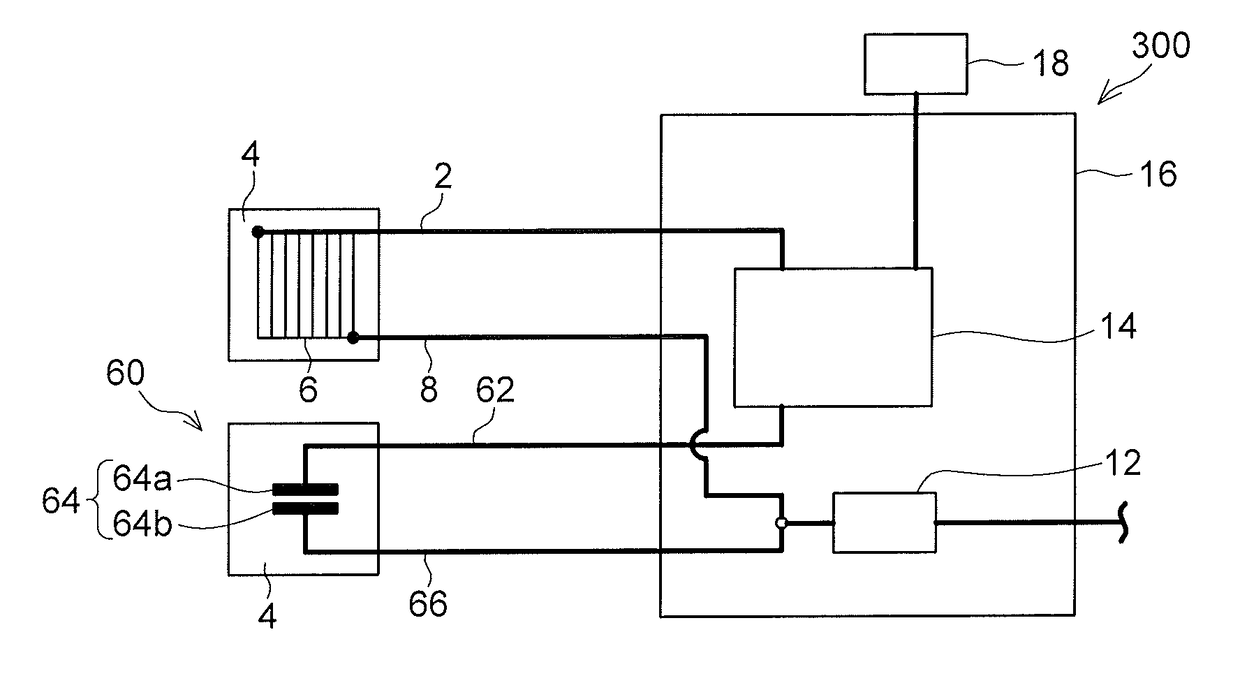
[0066]A fuel property sensor 300 is described with reference to FIG. 19. The fuel property sensor 300 is a modification of the fuel property sensors 100 and 200. The fuel property sensor 300 differs from the fuel property sensors 100 and 200 in that the fuel property sensor 300 includes a water detector 60. Components of the fuel property sensor 300 which are substantially identical to those of the fuel property sensors 100 and 200 are given the same reference numerals as those of the fuel property sensors 100 and 200, and as such, may not be described below.
[0067]The water detector 60 includes an electrode pair 64. The electrode pair 64 is provided on the front surface of the substrate 4. The electrode pair 64 includes a first electrode 64a and a second electrode 64b spaced from the first electrode 64a. A third lead wire 62 is connected to the first electrode 64a, and a fourth lead wire 66 is connected to the second electrode 64b. The third lead wire 62 is connected to the signal o...
PUM
| Property | Measurement | Unit |
|---|---|---|
| distance | aaaaa | aaaaa |
| conductive | aaaaa | aaaaa |
| electrical conductivity | aaaaa | aaaaa |
Abstract
Description
Claims
Application Information
 - R&D
- Intellectual Property
- Life Sciences
- Materials
- Tech Scout
- Unparalleled Data Quality
- Higher Quality Content
- 60% Fewer Hallucinations
Browse by: Latest US Patents, China's latest patents, Technical Efficacy Thesaurus, Application Domain, Technology Topic, Popular Technical Reports.
© 2025 PatSnap. All rights reserved.Legal|Privacy policy|Modern Slavery Act Transparency Statement|Sitemap|About US| Contact US: help@patsnap.com


