Fixture for supporting a workpiece

a technology for fixing workpieces and workpieces, applied in the field of fixing workpieces, can solve the problems of difficult to accurately hold workpieces while machining workpieces, high cost of processes, etc., and achieve the effects of reducing manufacturing operations, reducing manufacturing costs, and reducing manufacturing costs

Active Publication Date: 2018-08-21
GM GLOBAL TECH OPERATIONS LLC +1
View PDF56 Cites 0 Cited by
  • Summary
  • Abstract
  • Description
  • Claims
  • Application Information

AI Technical Summary

Benefits of technology

[0007]An advantage of an embodiment is that the fixture incorporates a non-deck face manufacturing location, yet renders a machined part that is essentially machined from the desired deck face. The fixturing allows for access to five faces of a cylinder head for manufacturing operations to be performed on the head. The number of clamping positions can be minimized, resulting in fewer loads and unloads of the component, and thus a fewer number of manufacturing operations. The access to five faces of a cylinder head may also allow for reduced tool length for tools used to process the head, and may improve tolerances in the finished parts.

Problems solved by technology

Holding a workpiece and positioning it accurately while machining the workpiece performing multiple operations on it is challenging.
However, these processes can be costly and may require extensive part features to be designed into the workpiece, such as a cylinder head.

Method used


Image

  • Fixture for supporting a workpiece
  • Fixture for supporting a workpiece
  • Fixture for supporting a workpiece

Examples


Embodiment Construction

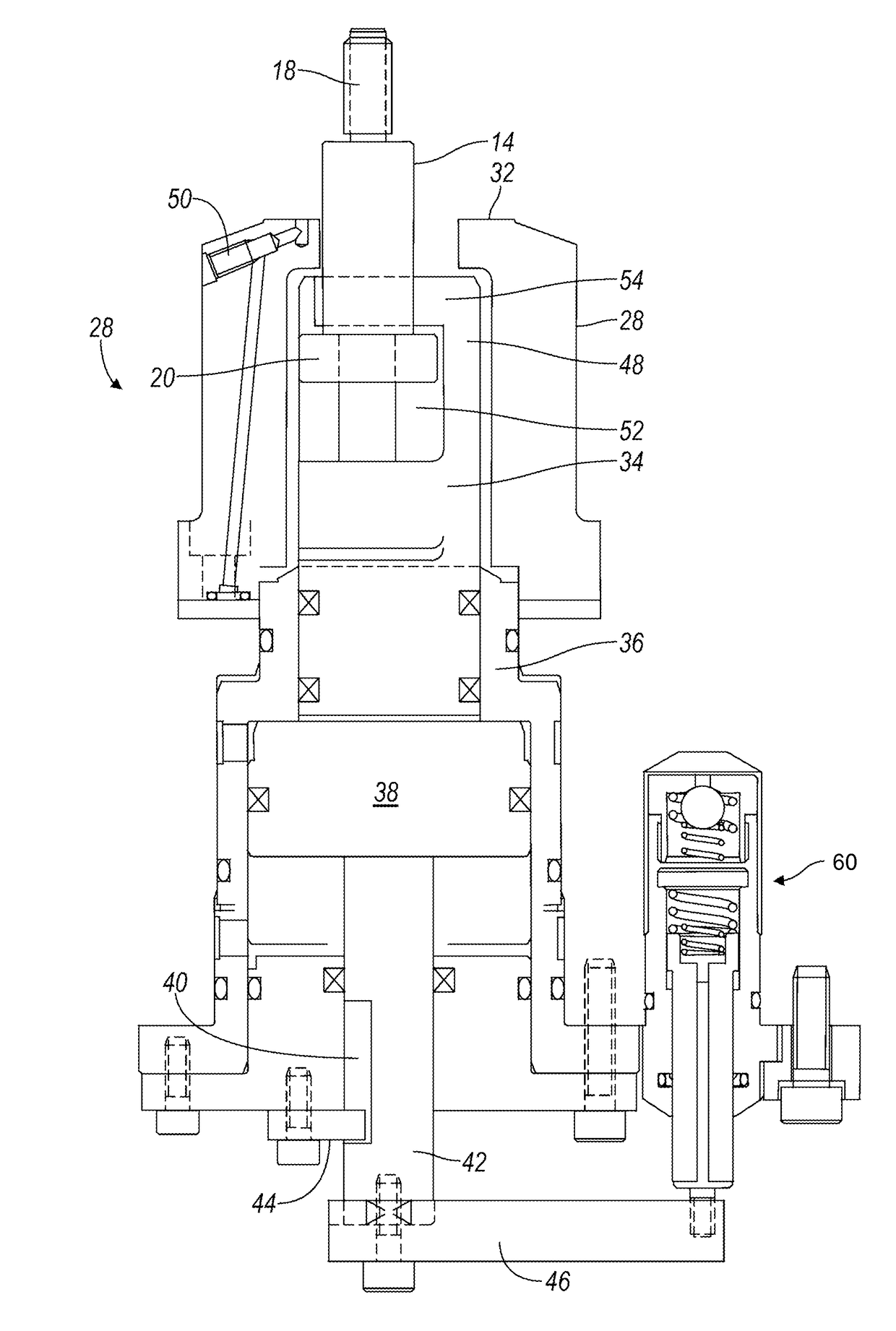
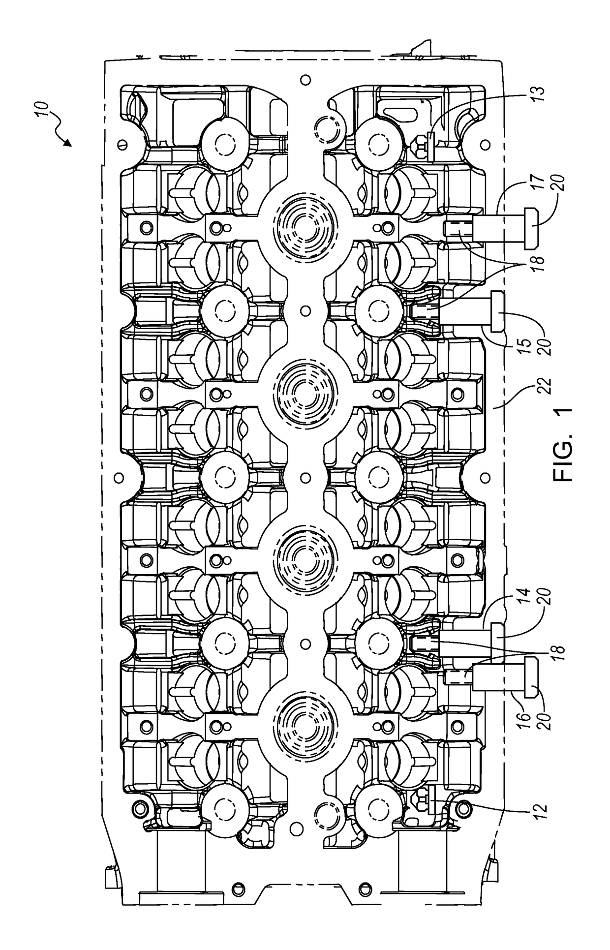
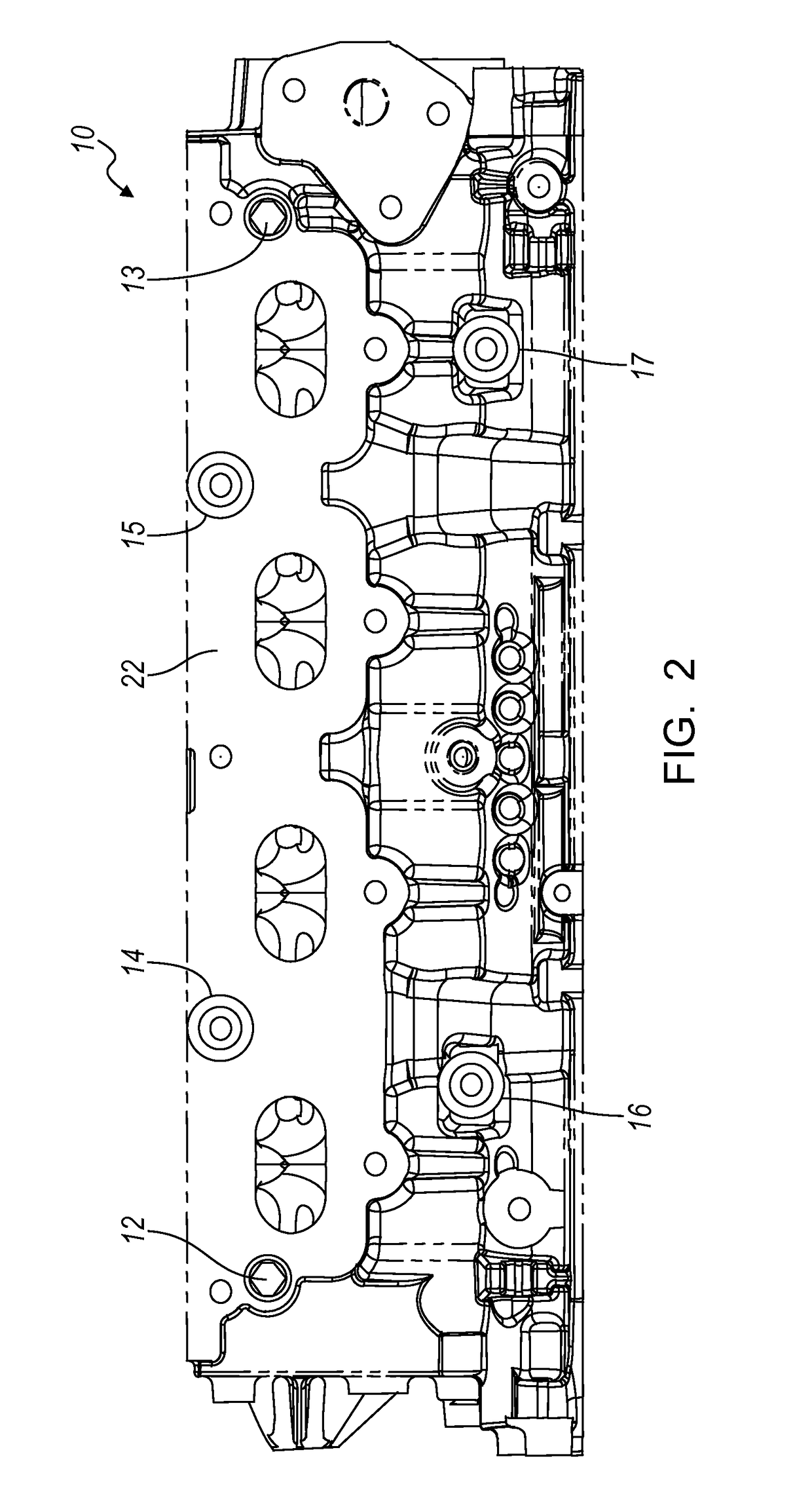
[0013]Referring to FIGS. 1 and 2, a cylinder head 10 for an internal combustion engine (not shown) includes locating pins 12, 13, formed with concave surfaces, and threaded bores for receiving tie rods 14, 15, 16, 17. A threaded shank 18 of each tie rod 14-17 is engaged with the threaded bores formed in the cylinder head 10. The head 20 of each tie rod extends outward from the exhaust face 22 of the cylinder head 10 and is sized and shaped to be received and selectively retained in a fixture assembly. Each tie rod 14-17 includes a cylindrical shank, located between the threaded shank 18 and the head 10, the cylindrical shank extending mutually parallel to the cylindrical shanks of the other tie rods and perpendicular to the exhaust face 22.

[0014]FIGS. 3 and 4 show a fixture assembly 24 comprising an upper, quick connect (QC) fixture 26, which includes four clamping cartridges 28, each cartridge engaged with the head 20 of each tie rod 14-17, a locating pin 30 having a convex surface...


PUM

PropertyMeasurementUnit
lengthaaaaaaaaaa
displacementaaaaaaaaaa
timeaaaaaaaaaa

Abstract

A fixture for holding a workpiece includes clamps configured to engage tie rods secured to the workpiece, locating pins configured to engage a corresponding pin secured to the workpiece, pads, and actuators configured to move clamps for alternately drawing the workpiece into contact with the pads and disengaging the tie rod from the clamp such that the fixture assembly can release the workpiece.

Description

CROSS REFERENCE TO RELATED APPLICATIONS[0001]This application claims priority to and the benefit of U.S. Provisional Application No. 61 / 431,417, filed Jan. 10, 2011, the full disclosure of which is incorporated herein by reference.BACKGROUND OF INVENTION[0002]The present invention relates generally to fixturing for holding a workpiece while performing manufacturing operations on the workpiece.[0003]Holding a workpiece and positioning it accurately while machining the workpiece performing multiple operations on it is challenging. This is especially true when tools used to process a complex-shaped workpiece must access the workpiece from multiple sides. For example, a cylinder head for an internal combustion engine may need to have operations performed that required access to several sides for multiple different operations to be performed on the head.[0004]Attempts have been made to machine and perform manufacturing processing on these types of workpieces by attaching adapter plates t...

Claims


Application Information

Patent Timeline
Patent Type & Authority Patents(United States)
IPC IPC(8): B23Q1/00B23B11/00B25B11/00B25B5/08B25B5/06
CPCB25B11/00B23B11/00B23Q1/009B23Q1/0081B25B5/061B25B5/087B23Q1/0072Y10T29/49998B23Q3/06B23Q3/18B25B11/02F02F1/00
Inventor HACKER, BRIAN F.TOMKIEWICZ, GREGORY J.GIORDA, CLAUDIOURSO, GIUSEPPE
Owner GM GLOBAL TECH OPERATIONS LLC
Why Eureka
Try Eureka