
Arrangement for light sheet microscopy

a technology of arrangement and light, applied in the field of arrangement of light sheet microscopy, can solve the problems of time-consuming, disrupting normal laboratory procedures, and reducing the accuracy of image processing, so as to eliminate imaging errors

Active Publication Date: 2018-08-14
CARL ZEISS MICROSCOPY GMBH
View PDF12 Cites 7 Cited by
  • Summary
  • Abstract
  • Description
  • Claims
  • Application Information

AI Technical Summary

Benefits of technology

The invention aims to correct imaging errors caused by obliquely passing light through an object. It introduces a simple corrective element that can be used with existing objectives and compensates for spherical aberrations. The corrective element can be used with different combinations of sample vessel, coverslip, and medium. Overall, the invention improves the accuracy and reliability of imaging techniques.

Problems solved by technology

Further, this method has the least light stress on the samples, which, among other things, reduces the risk of photobleaching of the sample because the sample is only illuminated by a thin light sheet at an angle to the detection direction not equal to zero.
However, this method of light sheet microscopy has some drawbacks.
Preparation of the samples in special cylindrical tubes which are filled with agarose gel is time-consuming and disrupts normal laboratory procedures; it is not compatible with standardized sample preparations or standardized sample holders.
Further, the inevitable difference in refractive index between the cylindrical tubes of glass or plastic and the agarose gel leads to optical aberrations which can impair resolving power.
Further, as a result of the sample preparation and the dimensions of the sample chamber, the light sheet is relatively thick and accordingly limits the attainable axial resolution.
Microtiter plates—also known as multi-well plates—which are standard in many branches of biology, and precisely also in fluorescence microscopy analysis of individual cells, cannot be used with this method because the objectives cannot be immersed in the very small wells that are arranged in grid shape on the plate.
A further disadvantage consists in that it is not readily possible with this construction to analyze a large number of samples within a short period of time (high-throughput screening) because the objectives must be cleaned when changing samples in order to avoid contaminating the different samples.
However, this advantage comes at the cost of a further, grave disadvantage because as a result of using the separating layer system—for example, the coverslip or vessel bottom with adjoining air layer—extreme imaging aberrations such as spherical aberrations and coma occur even at low numerical apertures NA of, e.g., 0.3 because the light to be detected or the illumination light passes obliquely through the interfaces of the separating layer system and correct imaging is no longer possible when using standardized rotationally symmetrical objectives.
However, no concrete specifications are given as to how such corrective means can be designed.
In addition, the proposed corrective lenses are only arranged in the objective behind the front lens, which makes it difficult to retrofit existing objectives.

Method used


Image

  • Arrangement for light sheet microscopy
  • Arrangement for light sheet microscopy
  • Arrangement for light sheet microscopy

Examples


Embodiment Construction

[0050]It is to be understood that the figures and descriptions of the present invention have been simplified to illustrate elements that are relevant for a clear understanding of the present invention, while eliminating, for purposes of clarity, many other elements which are conventional in this art. Those of ordinary skill in the art will recognize that other elements are desirable for implementing the present invention. However, because such elements are well known in the art, and because they do not facilitate a better understanding of the present invention, a discussion of such elements is not provided herein.

[0051]The present invention will now be described in detail on the basis of exemplary embodiments.

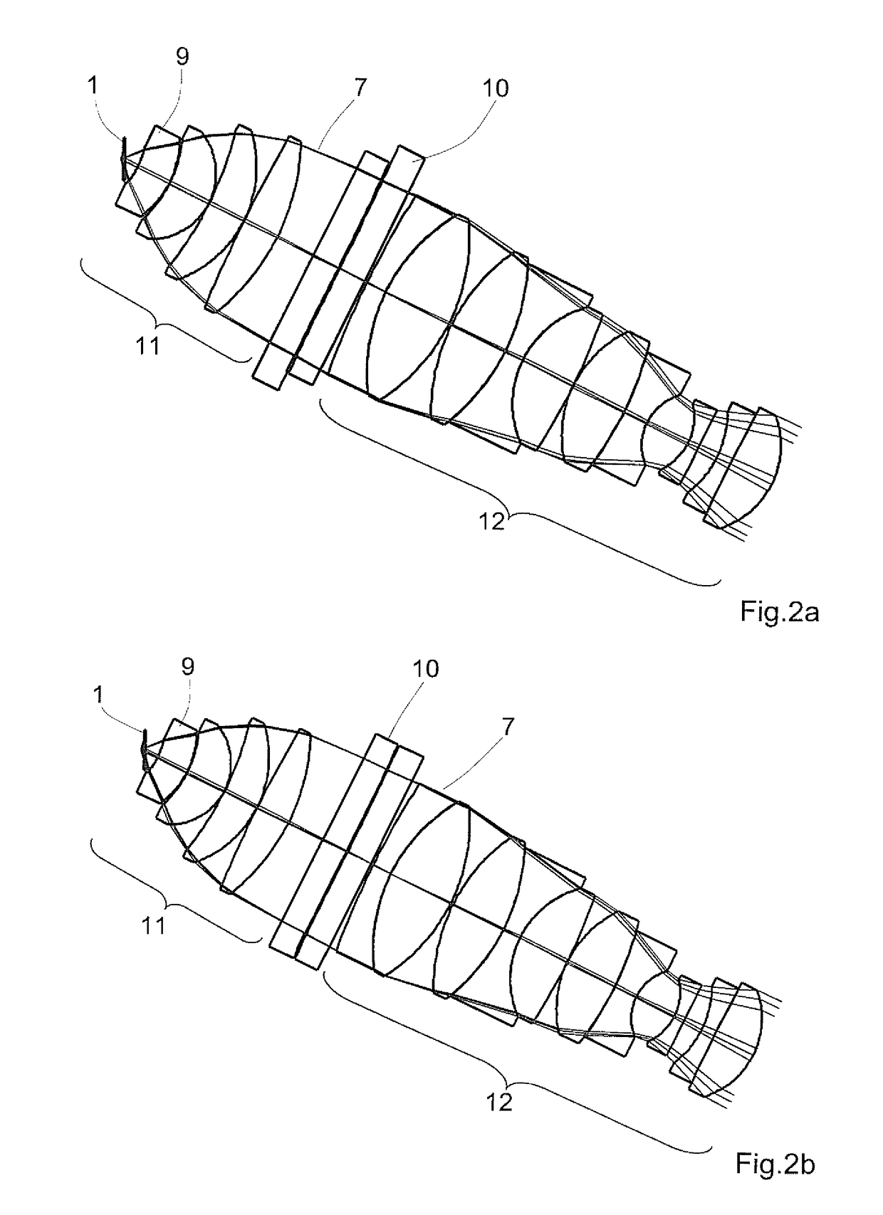
[0052]While the examples described in the following refer explicitly to a detection objective, they can also be readily applied to an illumination objective.

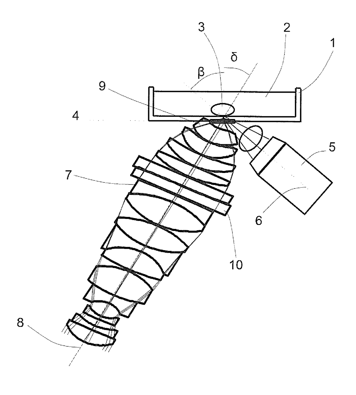
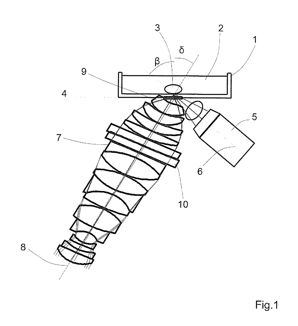
[0053]First, FIG. 1 shows the basic construction of an arrangement for light sheet microscopy. This arrangement comprises...


PUM


Abstract

An arrangement for light sheet microscopy including illumination optics with an illumination objective for illuminating a sample, located in a medium on a sample carrier aligned with respect to a plane reference surface, with a light sheet. The arrangement further includes detection optics with a detection objective. The arrangement also includes a separating layer system with at least one layer separating the medium from the illumination and detection objectives. The separating layer system is aligned with a base surface parallel to the reference surface and contacts the medium by this base surface. At least one detection corrective lens, for reducing those aberrations occurring as a result of light to be detected passing obliquely through interfaces of the separating layer system, is configured as free-form lens and is arranged between the detection objective and the separating layer system. Alternatively, it also forms the front lens of the detection objective.

Description

[0001]The present application claims priority from PCT Patent Application No. PCT / EP2014 / 074487 filed on Nov. 13, 2014, which claims priority from German Patent Application No. DE 10 2013 112 595.6 filed on Nov. 15, 2013, the disclosures of which are incorporated herein by reference in their entirety.FIELD OF THE INVENTION[0002]It is noted that citation or identification of any document in this application is not an admission that such document is available as prior art to the present invention.[0003]The invention is directed to an arrangement for light sheet microscopy. An arrangement of this kind comprises illumination optics with an illumination objective for illuminating a sample with a light sheet via an illumination beam path, which sample is located on a sample carrier in a medium. The optical axis of the illumination objective and the light sheet lie in a plane which forms an illumination angle β not equal to zero with the normal lines of a plane reference surface with respe...

Claims


Application Information

Patent Timeline
Patent Type & Authority Patents(United States)
IPC IPC(8): G02B21/08G02B13/00G02B21/02G02B27/00G02B13/18G02B21/33G02B21/00G02B21/36
CPCG02B21/08G02B13/0095G02B13/18G02B21/02G02B27/0025G02B27/0068G02B21/33G02B21/367G02B21/0052G02B21/0076
Inventor PRETORIUS, MARCO
Owner CARL ZEISS MICROSCOPY GMBH
Learn More