
Time measuring circuit and temperature sensor circuit

a time measuring circuit and temperature sensor technology, applied in the field of time measuring circuits, can solve the problems of long time during which the measurement is carried out using the high-speed clock signal, inability to meet the measurement requirements, so as to achieve suitable delay time measurements, the risk of counter bits being insufficient is reduced, and the change of the delay time that is being the target of measurement is great

Active Publication Date: 2018-07-31
KK TOYOTA CHUO KENKYUSHO
View PDF7 Cites 0 Cited by
  • Summary
  • Abstract
  • Description
  • Claims
  • Application Information

AI Technical Summary

Benefits of technology

This approach prevents insufficiency in counter bits and allows suitable time measurements, even with significant changes in target time, by effectively managing the switch from low-speed to high-speed clock signals in both time and temperature sensor circuits.

Problems solved by technology

In such a time measuring circuit, when a change in the target time is large, for example, when the target time becomes prominently longer than the estimated value, time during which the measurement is carried out using the high-speed clock signal becomes long, and an insufficiency in the counter bits may occur.

Method used


Image

  • Time measuring circuit and temperature sensor circuit
  • Time measuring circuit and temperature sensor circuit
  • Time measuring circuit and temperature sensor circuit

Examples


embodiment

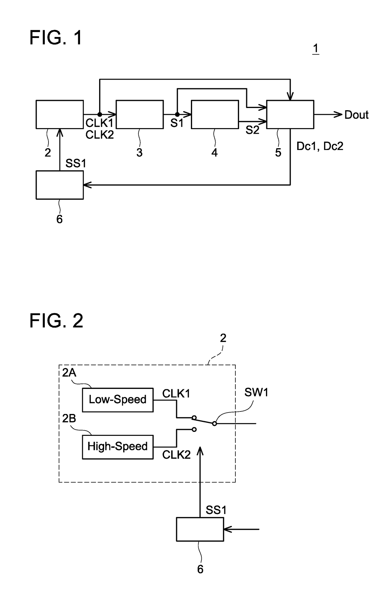
[0025]As shown in FIG. 1, a temperature sensor circuit 1 is a circuit integrated into one chip, and comprises an oscillating circuit 2, a frequency divider circuit 3, a delay circuit 4, a delay time measuring circuit 5, and a switching signal generating circuit 6.

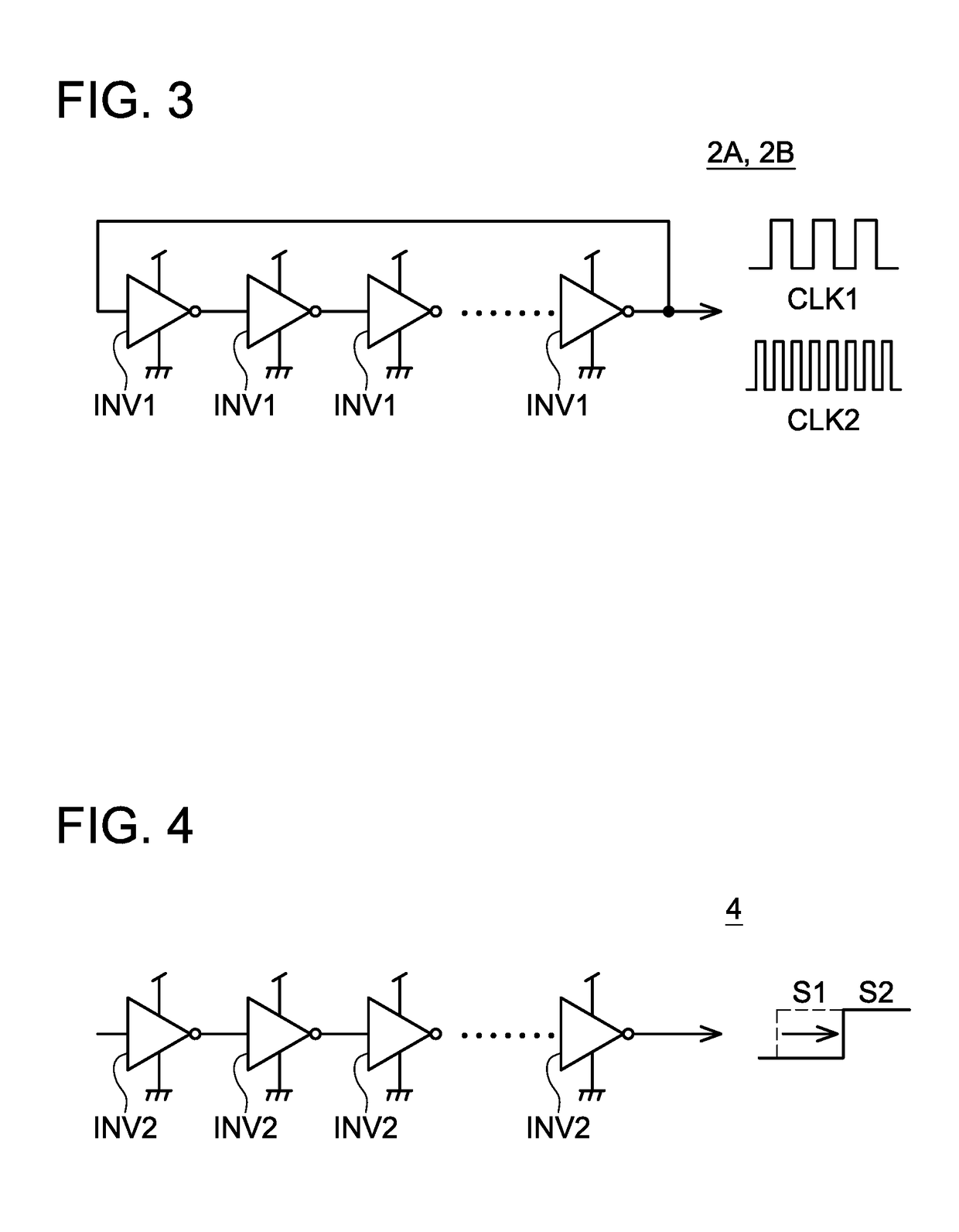
[0026]The oscillating circuit 2 is configured to generate a low-speed clock signal CLK1 with a relatively low frequency and a high-speed clock signal CLK2 with a relatively high frequency. These clock signals CLK1, CLK2 are for example rectangular waves with 50% duty ratio. The frequency divider circuit 3 is configured to convert the low-speed clock signal CLK1 to a low-frequency signal S1 having a low frequency. The frequency divider circuit 3 modulates the frequency of the low-speed clock signal CLK1 to a low frequency for example by 1 / 1024 times or 1 / 2048 times. The delay circuit 4 is configured to generate a delay signal S2 that is delayed from the low-frequency signal S1. The delay time measuring circuit 5 is configure...


PUM

PropertyMeasurementUnit
timeaaaaaaaaaa
speedaaaaaaaaaa
frequencyaaaaaaaaaa

Abstract

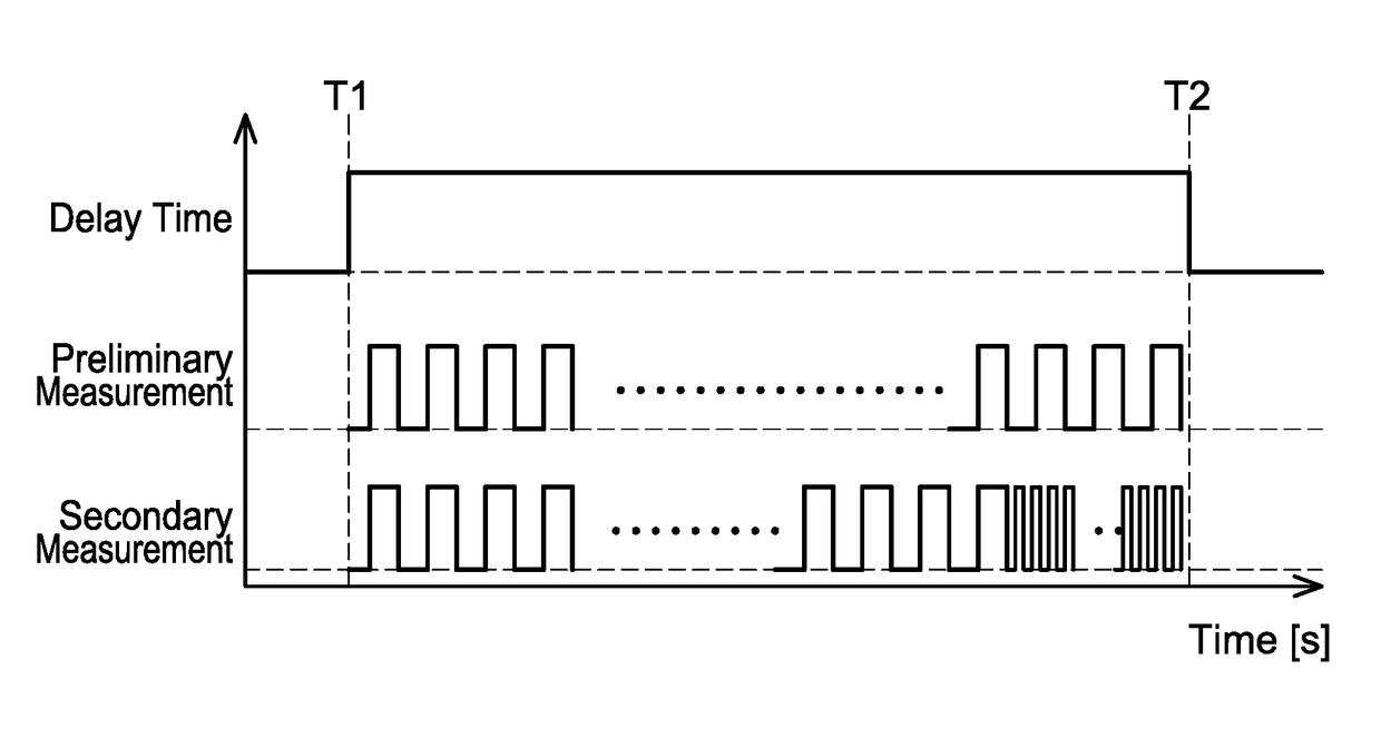
A time measuring circuit is provided with an oscillating circuit configured to generate a low-speed clock signal and a high-speed clock signal; and a measuring circuit configured to measure target time based on clock number of the low-speed clock signal and the high-speed clock signal outputted from the oscillating circuit, wherein the low-speed clock signal has a relatively low frequency and the high-speed clock signal has a relatively high frequency. The oscillating circuit is configured to switch from outputting the low-speed clock signal to outputting the high-speed clock signal when elapsed time from when a measurement of the target time started reaches a set value, and the set value is calculated by subtracting a predetermined value from a preliminary value which is provided by a preliminary measurement measuring the target time using only the low-speed clock signal.

Description

CROSS-REFERENCE TO RELATED APPLICATION[0001]This application claims priority to Japanese Patent Application No. 2015-050283 filed on Mar. 13, 2015, the entire contents of which are hereby incorporated by reference into the present application.TECHNICAL FIELD[0002]The technique disclosed herein relates to a time measuring circuit. The technique disclosed herein further relates to a temperature sensor circuit that is provided with the time measuring circuit.DESCRIPTION OF RELATED ART[0003]A time measuring circuit that measures time by using a clock signal is known. Such a time measuring circuit is in demand in various situations. For example, Japanese Patent Application Publication No. 2013-185985 discloses a temperature sensor circuit provided with this type of time measuring circuit. In the temperature sensor circuit of Japanese Patent Application Publication No. 2013-185985, the time measuring circuit is used to measure delay time of a delay signal having temperature dependency.[00...

Claims


Application Information

Patent Timeline
Patent Type & Authority Patents(United States)
IPC IPC(8): G04F10/00G04F10/04G01K7/34
CPCG04F10/04G04F10/005G01K7/346
Inventor SHIMADA, HIDETOMIZUNO, KENTARO
Owner KK TOYOTA CHUO KENKYUSHO
Learn More