
Vehicle driving support system

Inactive Publication Date: 2006-06-15
ALPINE ELECTRONICS INC
View PDF18 Cites 21 Cited by
  • Summary
  • Abstract
  • Description
  • Claims
  • Application Information

AI Technical Summary

Benefits of technology

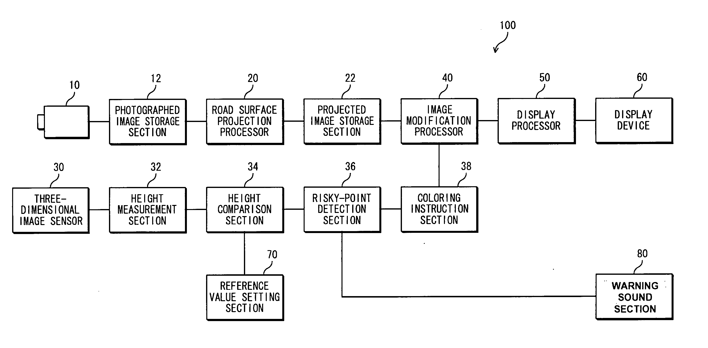
[0007] In one aspect of the invention, a vehicle driving support system is provided which comprises a camera for photographing an area surrounding a vehicle, the area including a road surface, a road surface projector operable to project an image of the area photographed by the camera to generate a projected image, a height detector operable to detect a height of an object existing in the area surrounding the vehicle, a height comparator operator to compare the height of the object with a reference value, a collision detector operable to detect a collision risk point associated with the object if the height of the object is determined to be approximately equal to or higher than the reference value by the height comparator, an image modifier operable to modify the projected image to emphasize the collision risk point, and a display operable to display the projected image after modification. Thus, the object located in the surrounding area and whose height is higher than the reference value is detected as the risky point, which is then displayed in an emphasized form. This allows a user (driver) to reliably identify the existence of the nearby object which has the height higher than the reference value and which may hit the vehicle.
[0008] More specifically, the emphasis of the risky point performed by the above-mentioned image modification section desirably involves coloring the risky point in a color other than that of the surrounding area. Particularly, the coloring preferably uses a plurality of colors depending upon the degree of possibility that the risky point may hit the vehicle. More preferably, the coloring involves coloring in red the risky point which will surely hit the vehicle, and coloring in yellow another risky point which may hit the vehicle. Alternatively, the emphasis of the risky point performed by the image modification section may involve causing the risky point to flash while a color of the point is changed at certain intervals. Preferably, the emphasis of the risky point performed by the image modification section may involve coloring a numeric value indicative of a height of the risky point. Further, the emphasis of the risky point performed by the image modification section may preferably involve causing the numeric value indicative of the height of the risky point to flash while a color of the numeric value is changed at certain intervals. The emphasis may permit the user to easily identify the risky point which may possibly hit the vehicle, and prevent the user from inadvertently missing the risky point.
[0009] The above-mentioned risky-point detection section preferably detects the risky point using the reference value corresponding to a height of lowermost parts of left and right doors of the vehicle. In this way, the user can learn the existence of the nearby object which may possibly hit the door when the door is opened, prior to the opening of the door.
[0010] Alternatively, the above-mentioned risky-point detection section may preferably detect the risky point using the reference value corresponding to a minimum road clearance of the vehicle. In this way, the user can learn whether or not the vehicle may pass over an obstacle or the like lying on a road surface, before the vehicle passes over that road surface.
[0013] Preferably, the system further comprises a warning sound section for generating a warning sound when the risky point is detected by the risky-point detection section. The warning sound may prevent the user inadvertently missing the existence of the risky point.

Problems solved by technology

Alternatively, the emphasis of the risky point performed by the image modification section may involve causing the risky point to flash while a color of the point is changed at certain intervals.

Method used


Image

  • Vehicle driving support system
  • Vehicle driving support system
  • Vehicle driving support system

Examples


Embodiment Construction

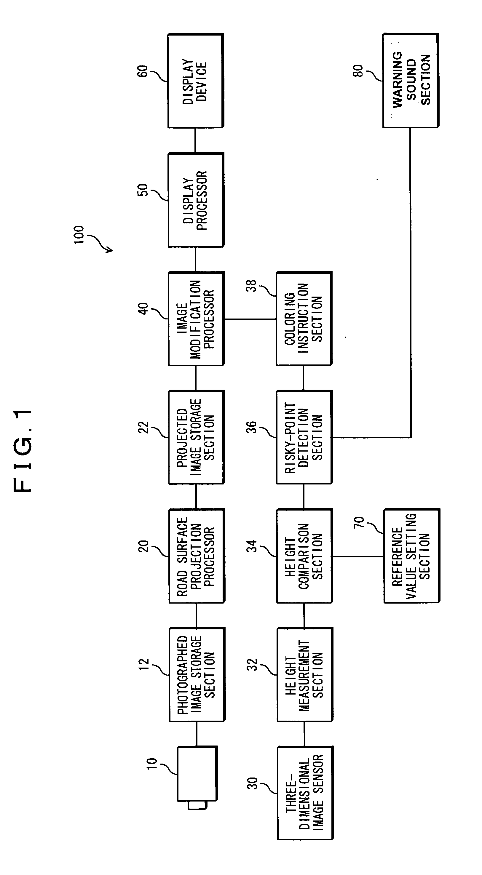
[0020] Reference will now be made in detail to exemplary embodiments, which are illustrated in the accompanying drawings. FIG. 1 shows a configuration of a vehicle driving support system according to the embodiment. A vehicle driving support system 100 shown in FIG. 1 includes a camera 10, a photographed image storage section 12, a road surface projection processor 20, a projected image storage section 22, a three-dimensional image sensor 30, a height measurement section 32, a height comparison section 34, a risky-point detection section 36, a coloring instruction section 38, an image modification processor 40, a display processor 50, a display device 60, a reference value setting section 70, and a warning sound section 80.

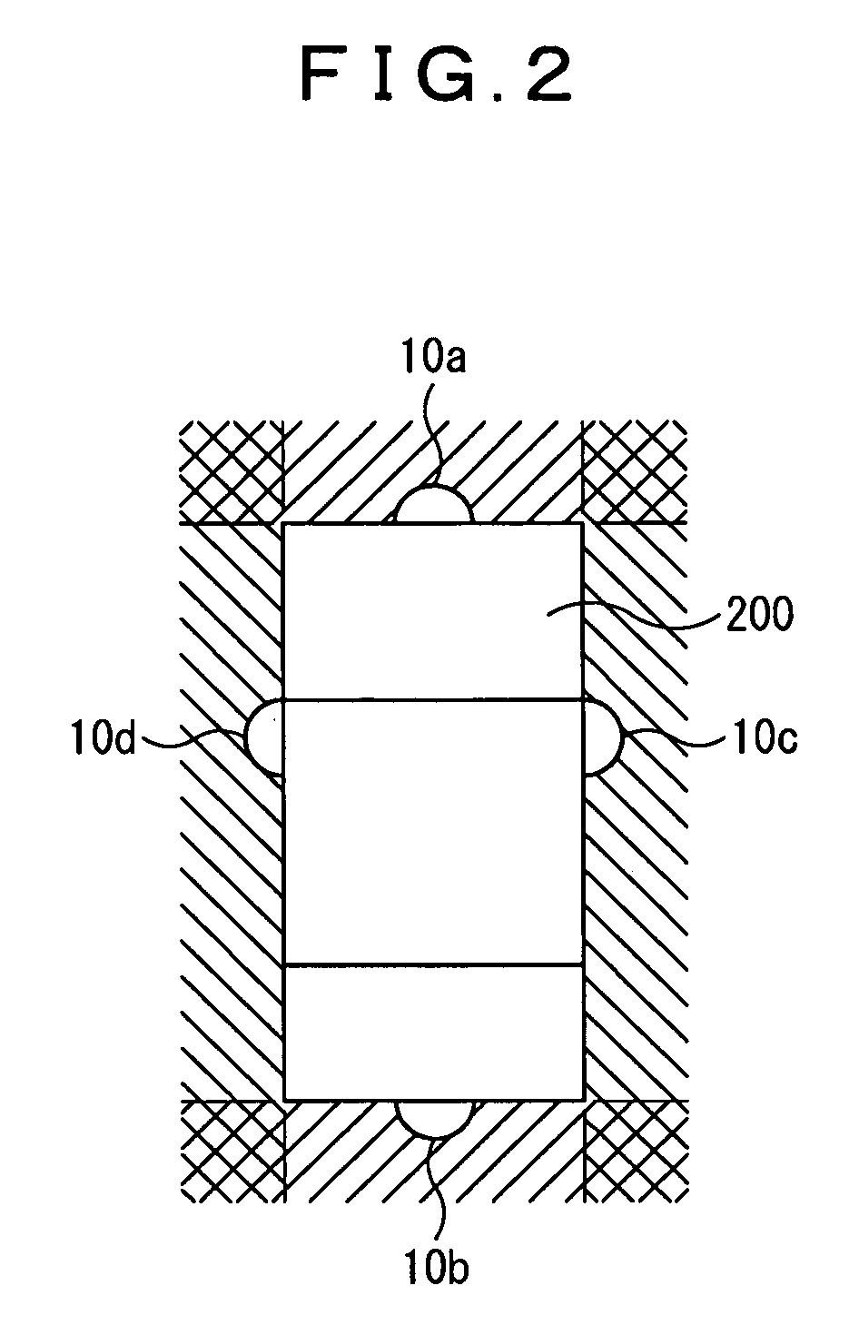
[0021] The camera 10 is operable to photograph an area surrounding a vehicle to create a side-view image. FIG. 2 illustrates a condition of installation of the cameras 10. A user's vehicle 200 has the cameras 10 (10a, 10b, 10c, and 10d) installed on four position...


PUM


Abstract

A vehicle driving support system is provided which can identify the existence of an object in a surrounding area of the vehicle which may possibly collide with the vehicle. The system comprises a camera for photographing the surrounding area of a vehicle, a road surface projector for projecting an image of the area photographed onto a road surface image, a three-dimensional image sensor and a height measurement section for detecting the height of an object existing in the surrounding area, a height comparator for comparing the height detected with a reference value, a collision detector for detecting a collision risk point whose height is higher than the reference value, an image modifier for emphasizing the collision risk point in the image generated by the road surface projector, and a display processor and display for displaying the image modified.

Description

BACKGROUND OF THE INVENTION [0001] 1. Field of the Invention [0002] The present invention relates to vehicle driving support systems for supporting driving of a vehicle by photographing an area surrounding the vehicle and displaying an image photographed on a screen. [0003] 2. Description of the Related Art [0004] An apparatus for indicating a condition of a surrounding area of a vehicle has hitherto been known which photographs the surrounding area using a vehicle-mounted camera, and displays an image photographed on a display device, as disclosed in, for example, JP-A-2001-114047 (see pages 2 to 6, and FIGS. 1 to 10). In this apparatus, a road surface projection process is performed on the photographed image to provide and display an image viewed from above and towards a road surface. Also, a rough height of an object located on the road is displayed in the image. [0005] In such an apparatus for indicating the vehicle surrounding condition as disclosed in the above-mentioned paten...

Claims


Application Information

Patent Timeline
IPC IPC(8): B60G17/016
CPCB60W30/08B60W50/14B60W2420/403B60W2420/42
Inventor OHKUBO, HITOMI
Owner ALPINE ELECTRONICS INC
Learn More