
Coated nanofiller/polymer composite sensor network for guided-wave-based structural health monitoring

a sensor network and composite technology, applied in the field of structural strain sensor network fabrication, can solve the problems of limited studies of coating technology that can be used to generate sensor networks fast and effectively, lack of development of distributed sensor networks for guided-wave-based impact/damage identification, and suffer from existing nanocomposite sensors

Active Publication Date: 2018-07-03
THE HONG KONG POLYTECHNIC UNIV
View PDF5 Cites 2 Cited by
  • Summary
  • Abstract
  • Description
  • Claims
  • Application Information

AI Technical Summary

Benefits of technology

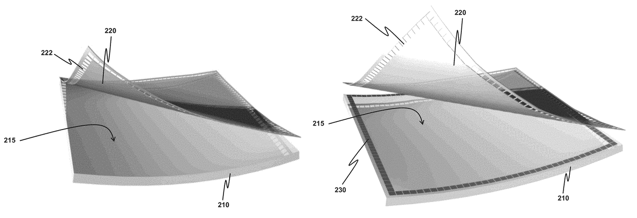
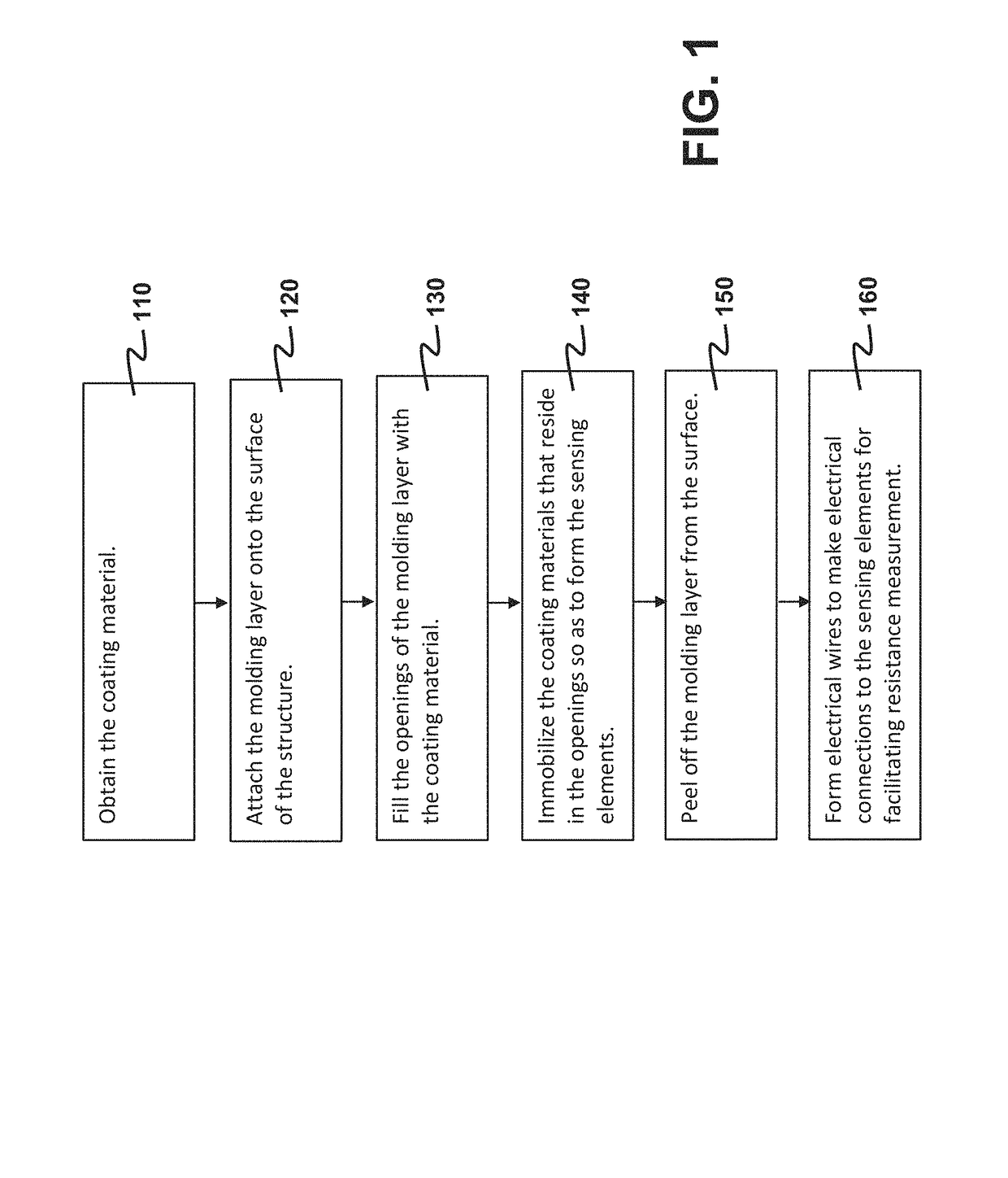
The present invention provides a method for creating a sensor network on a structure's surface. The method is efficient and effective in generating the network. Each sensor is made up of a thin layer of a special material called nanocomposite, which is placed on the floor according to a plan. The thickness of these layers is also pre-determined.

Problems solved by technology

However, existing nanocomposite sensors suffer from two major limitations: (1) limited studies of coating technologies that can be used to generate sensor networks fast and effectively; and (2) lacking of development in distributed sensor networks for guided-wave-based impact / damage identification.

Method used


Image

  • Coated nanofiller/polymer composite sensor network for guided-wave-based structural health monitoring
  • Coated nanofiller/polymer composite sensor network for guided-wave-based structural health monitoring
  • Coated nanofiller/polymer composite sensor network for guided-wave-based structural health monitoring

Examples


Embodiment Construction

[0026]As used herein, “a structure” means a combination of members connected together in such a way to serve a useful purpose. The useful purpose may be related to civil engineering and mechanical engineering, to name a few. Examples of the structure related to the domain of civil engineering include a building, a part thereof such as a wall, a dam and a bridge. In the domain of mechanical engineering, examples of the structure include a car, a train, an aircraft, a machine, a water pipe, an oil pipe, etc.

[0027]The present invention first provides a structural-strain sensor network having plural sensing elements and fabricated on a structure for measuring strains at different locations on a surface of the structure. The disclosed sensor network has dual advantages that its fabrication is quick and the sensor network has a high sensitivity (i.e. being effective). The present invention also provides a technique of using the disclosed sensor network to locate a damaged location on the ...


PUM

PropertyMeasurementUnit
temperatureaaaaaaaaaa
thicknessaaaaaaaaaa
resistanceaaaaaaaaaa

Abstract

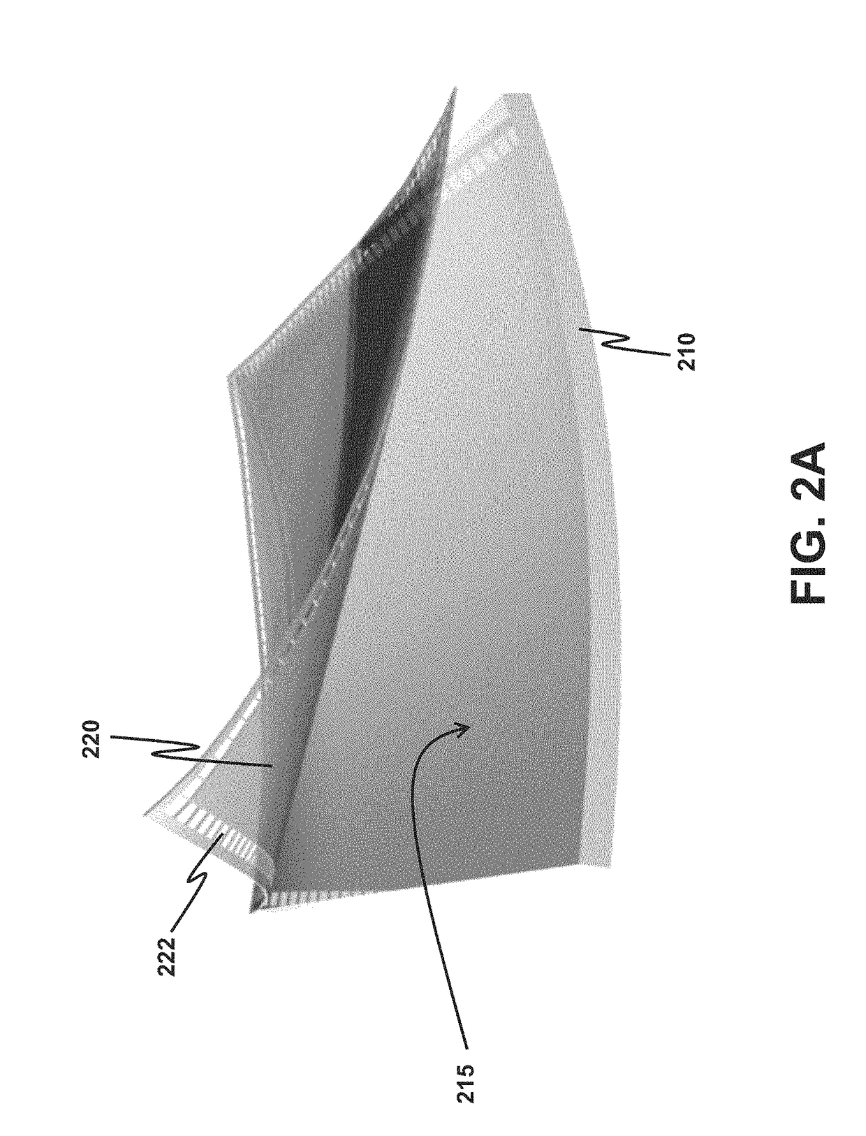
A method for forming a structural-strain sensor network on a structure is provided. The sensor network has plural nanocomposite sensing elements having high sensitivity, and can be quickly fabricated. The method comprises attaching a molding layer having openings onto the surface, and filling the openings with a coating material made of nanocomposite hybrid material. After immobilizing the coating material in the openings, the sensing elements are formed and the molding layer is removed. Electrical wires are formed on the surface such that two opposite electrodes are formed on each sensing element. The resistance between the two electrodes indicates a strain experienced. The sensor network finds applications in identifying a damaged location or an impact location on the structure for structural health monitoring. Voltage waveforms measured at the sensing elements are analyzed to estimate the damaged location or the impact location according to a guided-wave propagation model.

Description

FIELD OF THE INVENTION[0001]The present invention generally relates to a structural-strain sensor network made of nanocomposite hybrid material, for measuring a strain of a structure. In particular, the present invention relates to the fabrication of this sensor network and applications thereof for structural health monitoring (SHM).BACKGROUND[0002]Utilization of nanocomposite sensors for structural strain measurement has been widely studied. The basic mechanism of strain sensing is that a network formed by nanofillers is deformed in the presence structural strains, and such network deformation causes changes in the resistance value of a sensor formed by the nanofiller network. Thus, through resistance measurement, the levels of structural strains can be, in theory, captured and quantified.[0003]There are many different types of nanofillers, including carbon nanotube (CNT), carbon black (CB), graphene, etc. The types of polymer matrix for housing nanofillers can also be chosen from ...

Claims


Application Information

Patent Timeline
Patent Type & Authority Patents(United States)
IPC IPC(8): G01M5/00B33Y10/00G01M99/00B29C67/00G01L1/22B05D1/32B29L31/34
CPCG01L1/225B05D1/325B33Y10/00G01L1/2287B29C64/00G01M99/007B05D2520/10B05D2601/20B29L2031/34G01M5/0083G01L1/205G01L5/0052G01M5/0016G01M5/0025G01M5/0033G01M5/0041
Inventor SU, ZHONGQINGZHOU, LIMINZENG, ZHIHUILIU, MENGLONGXU, HAO
Owner THE HONG KONG POLYTECHNIC UNIV
Learn More