
Cooling method and cooling device for Al alloy manufactured casting

a cooling device and manufacturing casting technology, applied in the field of cooling method and cooling device for manufactured casting, can solve the problems of futile heating and cooling of quenched and cooled al alloy casting, and achieve the effects of reducing the variation in the strength of the whole product, reducing the differences in size, and reducing the difficulty of heating

Active Publication Date: 2018-06-19
MAZDA MOTOR CORP
View PDF22 Cites 0 Cited by
  • Summary
  • Abstract
  • Description
  • Claims
  • Application Information

AI Technical Summary

Benefits of technology

The present invention is about a method and device for cooling Al alloy castings that reduces strength variations and deformation, resulting in less variation in size between parts that need to be the same age. This makes the castings easier to age.

Problems solved by technology

This requires futile work of heating the quenched and cooled Al alloy casting.

Method used


Image

  • Cooling method and cooling device for Al alloy manufactured casting
  • Cooling method and cooling device for Al alloy manufactured casting
  • Cooling method and cooling device for Al alloy manufactured casting

Examples


Embodiment Construction

[0049]An embodiment of the present invention will be described hereinafter in detail with reference to the drawings.

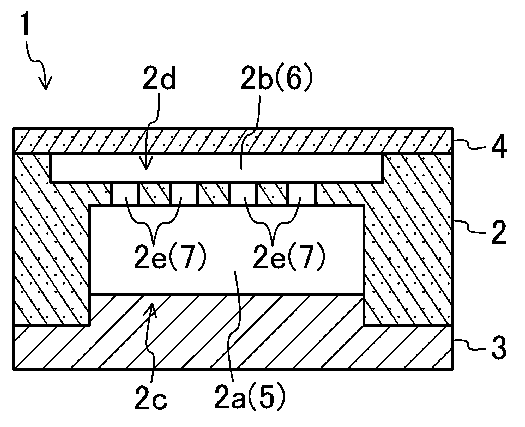
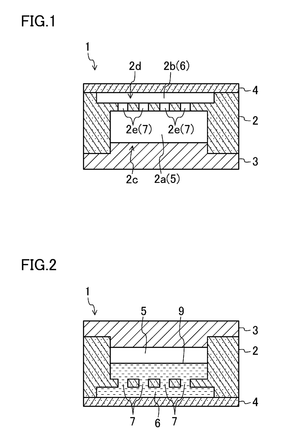
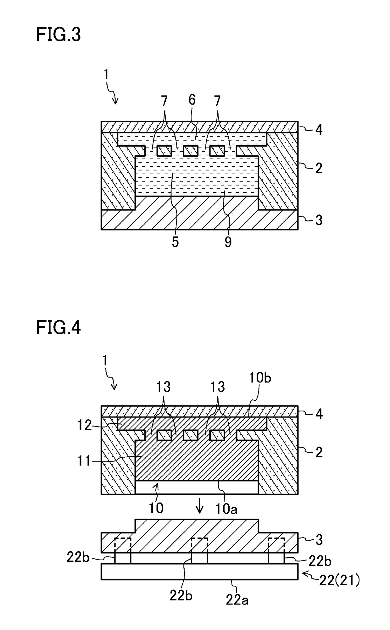
[0050]FIG. 1 illustrates a mold 1 for forming an Al alloy casting. In this mold 1, a cavity 5 and a feeder head cavity 6 are arranged vertically. The mold 1 includes a mold body 2, a first closing member 3, and a second closing member 4, which are separable from each other.

[0051]The mold body 2 includes a first space 2a for the cavity 5, a second space 2b for the feeder head cavity 6, a first open portion 2c, a second open portion second 2d, and a plurality of communication portions 2e. The first open portion 2c exposes the first space 2a toward the opposite side of the second space 2b. The second open portion exposes the second space 2b toward the opposite side of the first space 2a. The plurality of communication portions 2e allow the first space 2a to communicate with the second space 2b. The plurality of communication portions 2e form a molten metal supply passage ...


PUM

PropertyMeasurementUnit
particle sizeaaaaaaaaaa

Abstract

A method includes product side showering of showering a first surface (the surface of a product (11) opposite to a feeder head (12)) of an Al alloy casting (10) including the product (11) and the feeder head (12) with mist of cooling liquid, and feeder head side showering of showering a second surface (the surface of the feeder head (12) opposite to the product (11)) of the Al alloy casting (10) with the mist of the cooling liquid. The feeder head side showering starts showering the second surface of the Al alloy casting (10) after a start and before an end of the product side showering to quench and cool the Al alloy casting (10) together with the product side showering.

Description

TECHNICAL FIELD[0001]The present invention relates to a method of cooling an Al alloy casting formed by injecting a molten Al alloy into a cavity and a feeder head cavity formed in a mold, and a device for cooling such an Al alloy casting.BACKGROUND ART[0002]In general, an Al alloy casting is formed in a mold including a cavity and a feeder head cavity. Thus, the formed Al alloy casting includes a product corresponding to the cavity and a feeder head corresponding to the feeder head cavity. The feeder head is eventually cut off from the product. For example, a cylinder head, cylinder blocks, etc., of an engine are casted as the product.[0003]The formed Al alloy casting (i.e., the product and the feeder head) is subjected to quenching (solution quenching) and aging in this order to increase the mechanical strength.[0004]In view of facility, conventional quenching is performed by putting (sinking) the Al alloy casting formed in the mold into stored water.[0005]The quenched and cooled ...

Claims


Application Information

Patent Timeline
Patent Type & Authority Patents(United States)
IPC IPC(8): B22D21/00B22D21/04C22F1/00C22F1/04B22D17/20C22C21/00B22D30/00
CPCC22F1/002B22D17/20B22D21/007B22D21/04B22D30/00C22C21/00C22F1/04
Inventor KUBOTA, TOMOHIDEYAMAMOTO, NAOAKIHASHIMOTO, SHUICHIMISAWA, YASUYUKI
Owner MAZDA MOTOR CORP
Learn More