
High-temperature-resistant high-pressure-resistant ceramic strain gauge sensor and its package curing method

A sensor and high-pressure-resistant technology, applied in instruments, measuring devices, earth-moving drilling and mining, etc., can solve the problems of limited service life of molded products, poor temperature and pressure resistance, and small signal receiving amplitude, achieving small deformation and improving Abrasion resistance, improved reception and repeatability

Inactive Publication Date: 2007-07-11
西安康培石油勘探技术工程服务有限公司
View PDF0 Cites 7 Cited by
  • Summary
  • Abstract
  • Description
  • Claims
  • Application Information

AI Technical Summary

Problems solved by technology

[0003] 1. The packaging structure is relatively complicated;
[0004] 2 The signal receiving range is relatively small and the repeatability is relatively poor;
[0005] 3. The temperature and pressure resistance of the formed product is relatively poor, and the operating temperature and pressure range are: 125°C, 45Mpa;
[0006] 4. The service life of molded products is limited, generally 6 to 12 months

Method used


Image

  • High-temperature-resistant high-pressure-resistant ceramic strain gauge sensor and its package curing method

Examples


Embodiment 1

[0034] A method for encapsulating and curing the product described in claim 1, carried out as follows:

[0035] 1) Clean the ceramic strain gauge, sensor housing and strain gauge holder with solvent oil or acetone;

[0036] 2) Put the ceramic strain gauge into the strain gauge fixing seat, and weld the electrode lead wires, and pay attention to face the negative electrode upward;

[0037] 3), weigh 1.5-2.5 grams of high-temperature epoxy resin A and curing agent B according to the ratio of 1:1, and place them in two containers respectively. The carbonization temperature of the high-temperature epoxy resin mentioned here is below 300 ° C;

[0038] 4) Put the weighed high-temperature epoxy resin and the installed sensor components into the incubator together, and preheat for 1:30 hours at a constant temperature of 75°C to 85°C;

[0039] 5) Preheat for 1:30 hours to take out the high-temperature epoxy resin, and at the same time pour high-temperature epoxy resin A and curing age...

Embodiment 2

[0045] According to the encapsulation curing method of product described in claim 2, carry out according to the following steps:

[0046] 1) Clean the ceramic strain gauge, sensor housing and strain gauge holder with solvent oil or acetone;

[0047] 2) Put the ceramic strain gauge into the strain gauge fixing seat, and weld the electrode lead wires, and pay attention to face the negative electrode upward;

[0048] 3), weigh 1.8-2.3 grams of high-temperature epoxy resin A and curing agent B according to the ratio of 1:1, and place them in two containers respectively. The carbonization temperature of high-temperature epoxy resin mentioned here is below 300 ° C;

[0049] 4) Put the weighed high-temperature epoxy resin and the installed sensor components together into the incubator, and preheat for 1:30 hours at a constant temperature of 77°C to 83°C;

[0050] 5) Preheat for 1:30 hours to take out the high-temperature epoxy resin, and at the same time pour high-temperature epoxy ...


PUM


Abstract

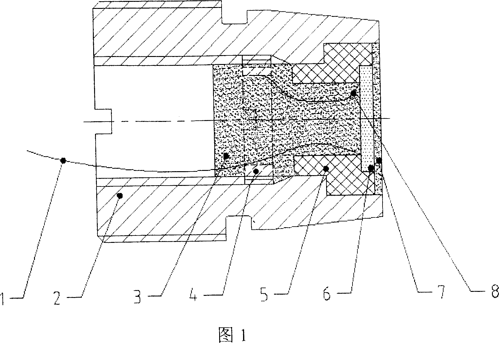
A high temperature and pressure resistant ceramic sensor and its sealing solidification method has a positive lead of the ceramic plate connected with one end of the ceramic strain foil, encapsulation film at the rear side of the sensor shell, copper ring connected with both sides of the rear encapsulation film, rear end encapsulation film and ceramic strain foil, the other side of the ceramic strain foil connected with the front encapsulation film, the other end of the ceramic foil connected with the negative lead of the ceramic strain foil, and the negative lead connected to the strain foil fixed base copper ring. The sealing and solidification method comprises the solution cleansing, welding the electrode lead, constant temperature preheating, encapsulation, constant temperature heating, abrasion, and testing the capacity value. It is simple in structure, convenient in use, long in duration; with improved signal receiving width and repeatability, with the resistant temperature reaching 150DEG C, pressure 60 MPa, limitless durability, free from maintenance, applicable in fields with distortion signal measuring and down whole ultrasonic flow meter.

Description

technical field [0001] The invention relates to a sensor and a method for encapsulating and curing the ceramic sensor, and is particularly suitable for a high temperature and high pressure resistant ceramic sensor and the method for encapsulating and curing the same. Background technique [0002] At present, the sensor packaged by the ultrasonic probe used in the ultrasonic flowmeter used for oil well and water well output and injection in the oil field is mainly to place the ceramic plate in a shell, and the two electrodes of the ceramic plate are drawn out through the high-pressure sealing plug, and the inner cavity of the shell Filled with transformer oil or silicone oil, the oil plays the role of insulation and pressure balance. The main defects of this packaging form are: [0003] 1. The packaging structure is relatively complicated; [0004] 2 The signal receiving range is relatively small and the repeatability is relatively poor; [0005] 3. The temperature and pres...

Claims


Application Information

Patent Timeline
IPC IPC(8): G01F1/66G01F15/00G01F15/02G01F15/10E21B47/00H01L49/00H01L21/50E21B47/017
Inventor 邓军安赵宏斌张超峰
Owner 西安康培石油勘探技术工程服务有限公司
Learn More