Device for shaving projection formed on flywheel and method of shaving projection

A trimming device and flywheel technology, applied in the directions of flywheel, electromechanical device, shearing device, etc., can solve the problems of impairing the perfect circularity of the yoke and reducing the accuracy of the protrusion position, and achieve the effect of improving the accuracy, improving the forming accuracy and eliminating the obstacles.

Inactive Publication Date: 2007-07-04
MITSUBA CORP
View PDF1 Cites 0 Cited by
  • Summary
  • Abstract
  • Description
  • Claims
  • Application Information

AI Technical Summary

Problems solved by technology

Therefore, even if the perfect circularity of the projection can be ensured in a single-piece product of the yoke, when the flywheel for fitting to the rotating shaft is integrated with the yoke by means such as riveting and fixing, there is a problem due to the aforementioned The force applied to the yoke by riveting will damage the roundness of the yoke and reduce the positional accuracy of the protrusions. These are the problems to be solved by the present invention.

Method used


Image

  • Device for shaving projection formed on flywheel and method of shaving projection
  • Device for shaving projection formed on flywheel and method of shaving projection
  • Device for shaving projection formed on flywheel and method of shaving projection

Examples


Embodiment Construction

[0028] Next, embodiments of the present invention will be described with reference to FIGS. 1 to 6 .

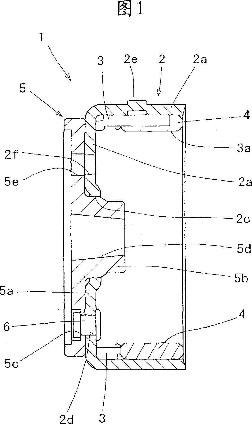
[0029] In the drawings, 1 is a flywheel constructed to fit externally on the crankshaft of an engine of a motorcycle, and a yoke 2 constituting the flywheel 1 is formed in a bottomed cylindrical shape from a ferromagnetic material (for example, iron). On the inner peripheral surface of the cylindrical portion 2a of the yoke 2, a magnet holder 3 is provided via an integral measure such as an adhesive, and the magnet holder 3 and the holding pin 3a disposed on the opening side of the yoke cylindrical portion 2a Many pairs of permanent magnets 4 are supported and fixed.

[0030] Further, a through hole 2c is opened in the cylindrical bottom 2b of the yoke 2 constituting the flywheel 1 in a positional relationship concentric with the axis of the cylindrical portion 2a, and a hub plate 5 is integrally provided on the outer surface of the cylindrical bottom 2b. The hub plate 5 is ...


PUM


Abstract

Triggering projections for obtaining a trigger signal can be shaved with high circularity, and the projections have an excellent sensing function as a trigger, where the projections are punched out in a projecting manner from the outer periphery of a yoke of a flywheel. A boss plate (5) is previously fixed by staking to a yoke (2) that forms a flywheel (1). A shaving device (7) is constructed such that a support shaft section (10), on which a boss tube section of the boss plate (5) is fitted, is provided on the fixed base (8) side and that a shaving die (15) is provided on a movable based (14) side, the shaving die (15) being co-axial with the support shaft section (10) and shaving a projection (2e) in the axial direction of the support shaft section (10).

Description

technical field [0001] The present invention relates to a trimming device and a trimming method of protrusions formed on a flywheel mounted on a rotating shaft for detecting rotation state. Background technique [0002] In general, among such flywheels, it is known that there is a flywheel in which permanent magnets are provided on the inner circumference of a cylindrical portion of a bottomed cylindrical yoke, and at the same time, a plurality of magnets are formed along the circumferential direction from the outer peripheral surface of the cylindrical portion to the outer diameter. The trigger protrusion protruding from the side is used to obtain the trigger signal; this flywheel is integrally embedded on the rotation shaft of the actuator, and on the other hand, the sensor is arranged opposite to the cylindrical part of the yoke, and by using the The sensor detects the magnetized protrusion and detects the rotational state of the rotary shaft (the driving state of the act...

Claims


Application Information

Patent Timeline
Patent Type & Authority Applications(China)
IPC IPC(8): H02K15/03B21D28/16B21D53/26
CPCB23D15/04F16F15/30H02K15/03
Inventor 堀内伸哉横尾次男出居勉福泽幸治伊藤泰人
Owner MITSUBA CORP
Why Eureka
Try Eureka