Antenna reflector machining device

A technology of processing device and reflective surface, applied in the field of antenna processing, can solve the problems of unfavorable update curve, low precision of processing device, etc., and achieve the effect of high roundness

Inactive Publication Date: 2017-05-10
TONGYU COMM INC
View PDF6 Cites 1 Cited by
  • Summary
  • Abstract
  • Description
  • Claims
  • Application Information

AI Technical Summary

Problems solved by technology

[0008] The main technical problem to be solved by the present invention is to provide a processing device for the antenna reflective surface, which can solve the problem of low precision of the reflective surface processing device in the prior art and is not conducive to updating the curve

Method used


Image

  • Antenna reflector machining device
  • Antenna reflector machining device
  • Antenna reflector machining device

Examples


Embodiment Construction

[0033] The following will clearly and completely describe the technical solutions in the embodiments of the present invention with reference to the accompanying drawings in the embodiments of the present invention. Obviously, the described embodiments are only some, not all, embodiments of the present invention. Based on the embodiments of the present invention, all other embodiments obtained by persons of ordinary skill in the art without making creative efforts belong to the protection scope of the present invention.

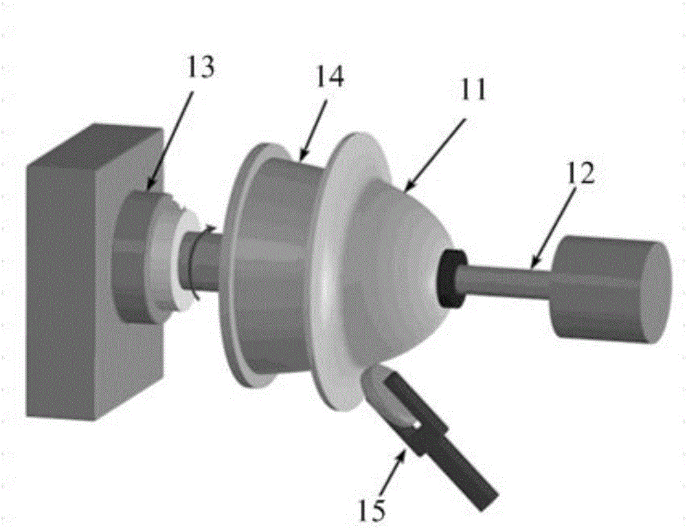
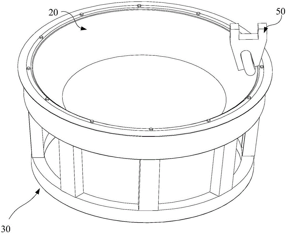
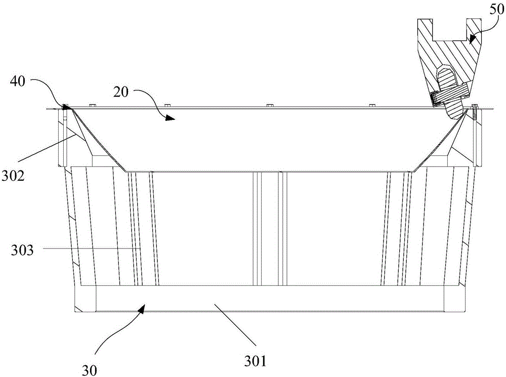
[0034] Please refer to Figure 2-4 , figure 2 It is a schematic diagram of a three-dimensional structure of an embodiment of a processing device for an antenna reflecting surface according to the present invention, wherein the machine tool is not shown; image 3 yes figure 2 The schematic diagram of the cross-sectional structure of the processing device shown; Figure 4 yes figure 2 Schematic diagram of the structure of the processing device shown in af...


PUM


Abstract

The invention discloses an antenna reflector machining device. The antenna reflector machining device is used for machining a material plate into a reflector and comprises a machine tool, a positioning frame, a fixing part and a cutter wheel component, wherein the positioning frame is fixedly mounted on the machine tool, the material plate is mounted and accommodated in the positioning frame, the fixing part is used for fixing the material plate on the positioning frame, and the cutter wheel component is used for pushing and pressing the material plate. The machine tool drives the positioning frame to rotate, and the cutter wheel component pushes and presses the surface, deviating from the positioning frame, of the material plate according to a preset program corresponding to an equation curve of the reflector so as to form the reflector. The antenna reflector machining device is capable of machining high-roundness reflectors and machining different types of reflectors by one die, thereby being applicable to different reflector curves.

Description

technical field [0001] The invention relates to the technical field of antenna processing, in particular to a processing device for an antenna reflection surface. Background technique [0002] In the prior art, according to the curve required for the microwave antenna reflection surface, a specific mold is formulated, and spinning is carried out in conjunction with a specific program, so that the material plate is plastically deformed to obtain a corresponding reflection surface. Specifically, see figure 1 , figure 1 It is a schematic diagram of the structural principle of the processing device for the antenna reflection surface in the prior art. The principle is as follows: [0003] 1: Place the material sheet 11 at a specific position on the machine tool (not marked); [0004] 2: Start the machine tool and fix the material plate through the tail top 12; [0005] 3: Start the machine tool spindle 13 to make it rotate, thereby driving the mold 14 to rotate; [0006] 4:...

Claims


Application Information

Patent Timeline
IPC IPC(8): B21D22/16
CPCB21D22/16
Inventor 粟炳龙窦华土张君
Owner TONGYU COMM INC
Why Eureka
Try Eureka