Reference clock sending circuit and method for light repeat plate

A reference clock and transmission circuit technology, applied in electrical components, electromagnetic repeaters, multiplex communication, etc., can solve the problems of service signal frequency deviation or frequency instability, and the inability to recognize service optical signal AIS alarms, etc. Achieve the effect of reducing cost overhead, improving maintainability and low cost

Inactive Publication Date: 2007-06-27
南京创码科技有限责任公司
View PDF0 Cites 0 Cited by
  • Summary
  • Abstract
  • Description
  • Claims
  • Application Information

AI Technical Summary

Problems solved by technology

[0004] When the optical signal input by the system has a quality problem, the optical transponder board loses a stable and reliable frequency source. At this time, the output service signal clock fails because there is no usable synchronization source, and the optical transponder board sends it to the downstream node. There will be obvious frequency deviation or frequency instability in the service signal, so the downstream node may not be able to recognize the AIS alarm inserted in the service optical signal

Method used


Image

  • Reference clock sending circuit and method for light repeat plate
  • Reference clock sending circuit and method for light repeat plate

Examples


Embodiment Construction

[0031] The technical solution and beneficial effects of the method of the present invention will be apparent through the detailed description of the preferred embodiments of the present invention in conjunction with the accompanying drawings.

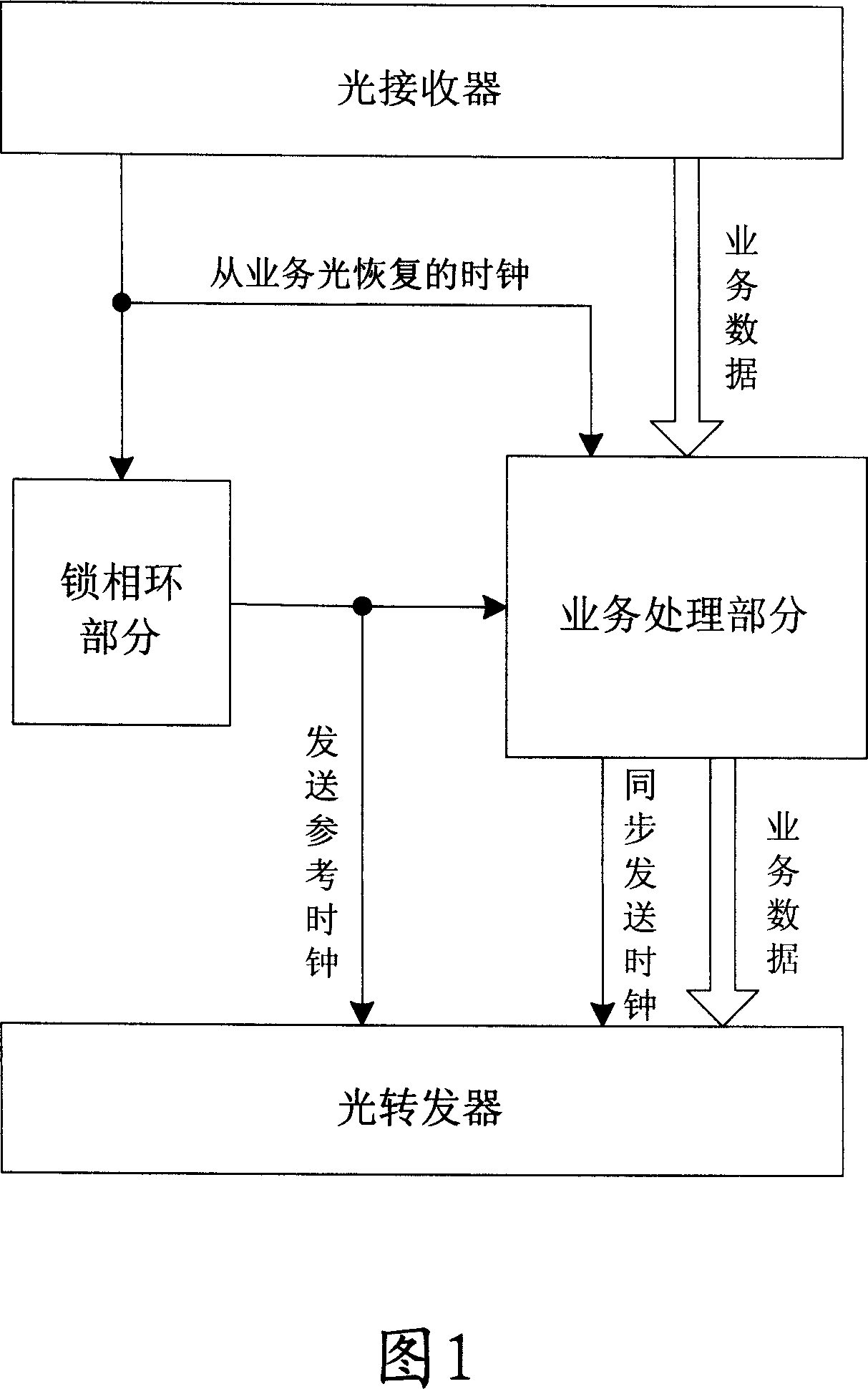
[0032] The reference clock sending circuit and method for the optical transponder of the present invention have been successfully applied to the DWDM optical transponder supporting SDH (Synchronous Digital Hierarchy, Synchronous Digital Hierarchy) services, as shown in Figure 1 It is a system block diagram of the optical transponder board according to the present invention, the system mainly includes an optical receiver, a phase-locked loop part, a service processing part and an optical transponder, wherein: the service light on the line side enters the optical receiver, and the optical receiving The optical transceiver extracts the service clock and data; the system service processing part will perform some overhead processing, and then...


PUM


Abstract

This invention discloses a transmission circuit of a reference clock used on a light transfer plate and a method, which adds three cheap devices of a D/A, a selector and a comparator, utilizes a VCO control voltage in a standard phase-locking ring to control and transmit a reference clock to be compared by a comparator and a D/A output voltage approaching to this time of error voltage when the input light service is normal, when the clock can't be used, the selector is used to select the stored D/A output voltage as the control voltage of VCO, when the clock is normal, the selector is used again to select a normal error voltage as the control voltage of the VCO so as to keep valid of reference clocks whether or not the input service optical clock is usable.

Description

technical field [0001] The invention relates to the field of optical communication equipment, in particular to a reference clock sending circuit and method used on an optical repeater board. Background technique [0002] In the WDM transmission system, the main function of the optical transponder board is to convert the service optical signal of any manufacturer that meets the requirements of the G.691 recommendation into an optical signal that meets the requirements of the G. Complete error correction coding, overhead detection processing. [0003] Inserting an alarm indication signal (AIS, Alarm IndicationSignal) into the output optical service signal is one of its overhead processing tasks: when the quality of the input optical signal of the system deteriorates and the service cannot be transmitted normally, the optical forwarding board needs to An AIS alarm is inserted into the service signal to notify the downstream node that the input service signal of the upstream no...

Claims


Application Information

Patent Timeline
Patent Type & Authority Applications(China)
IPC IPC(8): H04J3/06H04B10/16H04J14/02H04B10/29
Inventor 刘培元苑岩许鹍
Owner 南京创码科技有限责任公司
Why Eureka
Try Eureka