
Method for producing programmable device

A manufacturing method and device technology, applied in semiconductor/solid-state device manufacturing, electrical components, circuits, etc., can solve problems such as increasing production costs, increasing process steps and process integration complexity, and reducing production costs.

Inactive Publication Date: 2007-06-27
SHANGHAI HUA HONG NEC ELECTRONICS
View PDF0 Cites 0 Cited by
  • Summary
  • Abstract
  • Description
  • Claims
  • Application Information

AI Technical Summary

Problems solved by technology

This directly increases the complexity of process steps and process integration, increasing production costs

Method used


Image

  • Method for producing programmable device

Examples


Embodiment Construction

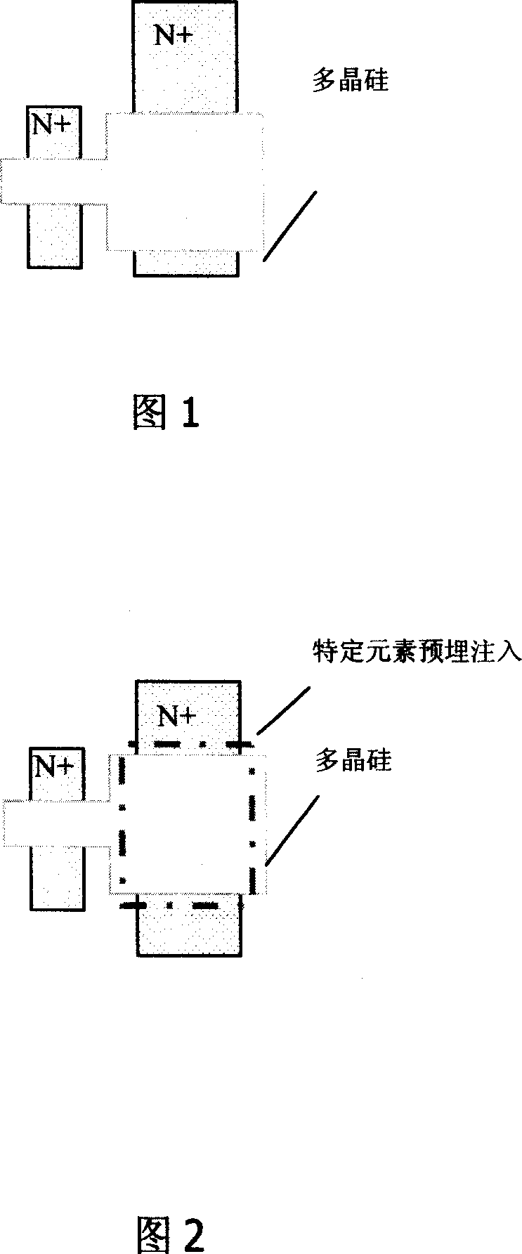
[0010] Fig. 2 is a schematic diagram of the structure of the programmable device of the present invention. As shown in FIG. 2 , the present invention is a method for fabricating a programmable device. The active region on the side of the capacitive transistor in the programmable device is pre-embedded and implanted with specific impurities, such as arsenic, before the gate oxide is formed.

[0011] The present invention pre-embeds and implants specific impurities in the active area on the capacitor side before forming the gate oxide, and can form a thicker oxide film in the active area on the capacitor side than the gate oxide film on the transistor side by adding only one implantation process step. membrane.

[0012] The present invention also has the following advantages: 1. The thickness of the oxide film can be increased without adding additional thermal oxidation, and the data storage time of the memory device can be improved; 2. The coupling efficiency is improved, there...


PUM


Abstract

This invention discloses a manufacturing method for programmable devices, in which, specific impurities are pre-burried in the active region at the side of a capacitive transistor before forming gate oxidation layer to form an oxidation film thicker than the grid oxidation film at the side of the transistor to increase the coupling effect of capacitive transistors and keep time for data greatly.

Description

technical field [0001] The invention relates to the field of manufacturing semiconductor integrated circuits and separate components, in particular to a method for manufacturing programmable devices. Background technique [0002] In the design of Single-Poly OTP Device (single-layer polycrystalline silicon one-time programmable device), how to improve the coupling efficiency of capacitive transistors is a key factor for the success or failure of device development in order to improve the programming efficiency and effect of the device. The Single-Poly OTP devices in the prior art are all realized by adopting N+ / NWell, P+ / PWell structures on the capacitive transistor side, or by making a barrier layer under the polysilicon. "A Single Poly EEPROM Cell Structure for Use in Standard CMOS Processes" (IEEE JOURNAL OF SOLID-STATECIRCUITS, VOL.24, NO.4, AUGUST 1989), "Cell and Circuit Design for Single-PolyEPROM" (IEEE JOURNAL OF SOLID-STATECIRCUITS, VOL.29, NO.3, march, 1994) and ...

Claims


Application Information

Patent Timeline
Patent Type & Authority Applications(China)
IPC IPC(8): H01L21/336H01L21/265
Inventor 徐向明龚顺强姚泽强
Owner SHANGHAI HUA HONG NEC ELECTRONICS
Learn More