
Device for long-distance transmitting Ethernet physical layer interface signal

A technology of physical layer signals and physical layer interfaces, which is applied in the field of devices for long-distance transmission of Ethernet physical layer interface signals, can solve the problems of interface timing confusion, unreliability, and occupation of connector terminals, etc., to reduce development costs, The effect of improving development efficiency

Inactive Publication Date: 2007-06-20
ZTE CORP
View PDF0 Cites 6 Cited by
  • Summary
  • Abstract
  • Description
  • Claims
  • Application Information

AI Technical Summary

Problems solved by technology

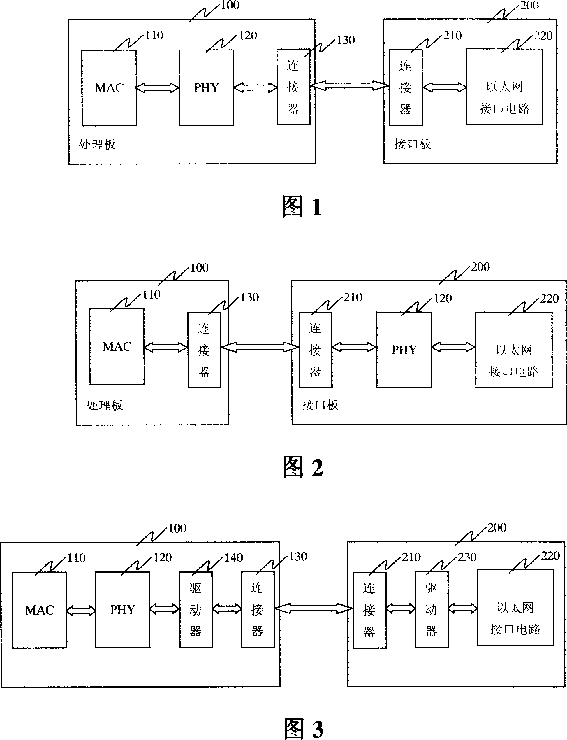
In this way, the distance between the PHY chip 120 and the Ethernet interface circuit 220 can be very close, but the distance between the MAC chip 110 and the PHY chip 120 increases.
Interfaces such as MII, RMII, SMII, SS-SMII, GMII, and TBI are usually used between the MAC chip 110 and the PHY chip 120. The maximum transmission distance of each interface is different, and the interface has many signal lines, which will occupy more connector terminals. , more importantly, the PHY chip 120 usually requires the MAC chip 110 to provide a reference clock, and the line delay of the clock after long-distance transmission is likely to cause confusion in the interface timing
Therefore, this design also has unreliability

Method used


Image

  • Device for long-distance transmitting Ethernet physical layer interface signal
  • Device for long-distance transmitting Ethernet physical layer interface signal
  • Device for long-distance transmitting Ethernet physical layer interface signal

Examples


Embodiment Construction

[0045]The implementation principle of the present invention is shown in FIG. 3 , and the device is mainly composed of two parts: a processing board 100 and an interface board 200 . The processing board 100 includes a MAC chip 110 , a PHY chip 120 , an Ethernet signal driver 140 , a signal connector 130 and the like. Standard interfaces such as MII, RMII, SMII, SS-SMII, GMII, and TBI are usually used between the MAC chip 110 and the PHY chip 120, and the Ethernet physical layer is between the PHY chip 120 and the driver 140 and between the driver 140 and the connector 130 The interface, that is, the Medium Dependent Interface (MDI), is compatible with 10BASE-T, 100BASE-TX, 100BASE-FX, 1000BASE-SX, 1000BASE-LX, 1000BASE-T and other standards according to the different types of Ethernet interfaces provided. The interface board 200 is relatively simple, mainly composed of an Ethernet interface circuit 220, an Ethernet signal driver 230, and a connector 210, and all parts are conne...


PUM


Abstract

The invention is concerned with the equipment that achieves long distance transmission by using Ethernet physical layer signal, includes: the processing board and the interface board, the processing board consists of the control chip access with the Ethernet medium, the Ethernet signal driver and the information connector, the medium accesses into the control chip connecting with the physical layer chip, the physical layer chip and the signal driver, the signal diver and the signal connector connect with the interface through the Ethernet physical layer; the interface board includes the Ethernet interface electric circuit, the Ethernet signal driver and the signal connector, the interface electric circuit and the signal driver, the signal driver and the signal connector connect with the interface through the Ethernet physical layer.

Description

technical field [0001] The invention relates to a device providing an Ethernet interface, in particular to a device for realizing long-distance transmission of Ethernet physical layer interface signals. Background technique [0002] Many devices that provide Ethernet interfaces need to provide Ethernet interfaces on the user side. The types of Ethernet interfaces currently provided mainly include: 10M / 100M electrical interface, 100M optical interface, 1000M optical / electrical interface, etc. Due to the flexibility and diversity of Ethernet technology applications, Ethernet devices are often required to provide flexible and diverse Ethernet interfaces, so equipment developers sometimes need to develop a device for each rate and each type of interface . [0003] In fact, with the development of chip technology, Ethernet MAC (Media Access Control) chips and PHY (Physical Layer) chips can be compatible with 10M / 100M / 1000M speed and optical / electrical interface , capable of in...

Claims


Application Information

Patent Timeline
Patent Type & Authority Applications(China)
IPC IPC(8): H04L12/02H04L29/08
Inventor 罗文
Owner ZTE CORP
Learn More