Fuel jet device of engine

A fuel injection device and fuel injection technology, applied in fuel injection pumps, fuel injection control, engine control, etc., can solve the problems of output unstable voltage, difficulty in correctly outputting 0V, cost increase, etc., and achieve high-precision fuel control, The effect of improving detection accuracy and improving control accuracy

Inactive Publication Date: 2007-06-06
MITSUBISHI ELECTRIC CORP
View PDF1 Cites 7 Cited by
  • Summary
  • Abstract
  • Description
  • Claims
  • Application Information

AI Technical Summary

Problems solved by technology

[0013] In the case of conventional general-purpose operational amplifiers used in fuel injection devices for engines, there is a problem that the battery negative power supply (0V) cannot be output or an unstable voltage can be output when the solenoid current does not flow.
[0014] In addition, when using an operational amplifier that can output a voltage close to the battery negative power supply (0V), the problem is that it will increase the cost, and it is difficult to output 0V accurately, so the desired fuel injection accuracy cannot be obtained in the end.
[0015] Furthermore, although a technical scheme has been proposed to measure the capacitor voltage, detect the energy stored in the capacitor, and detect the energizing current of the electromagnetic coil at the same time, and correct the driving time, the electrostatic capacitance and internal impedance of the capacitor are changed due to various deteriorations and errors. Therefore, the problem is that the driving time of the electromagnetic coil cannot be corrected correctly even if the capacitor voltage is measured

Method used


Image

  • Fuel jet device of engine
  • Fuel jet device of engine
  • Fuel jet device of engine

Examples


Embodiment Construction

[0032] Embodiment 1

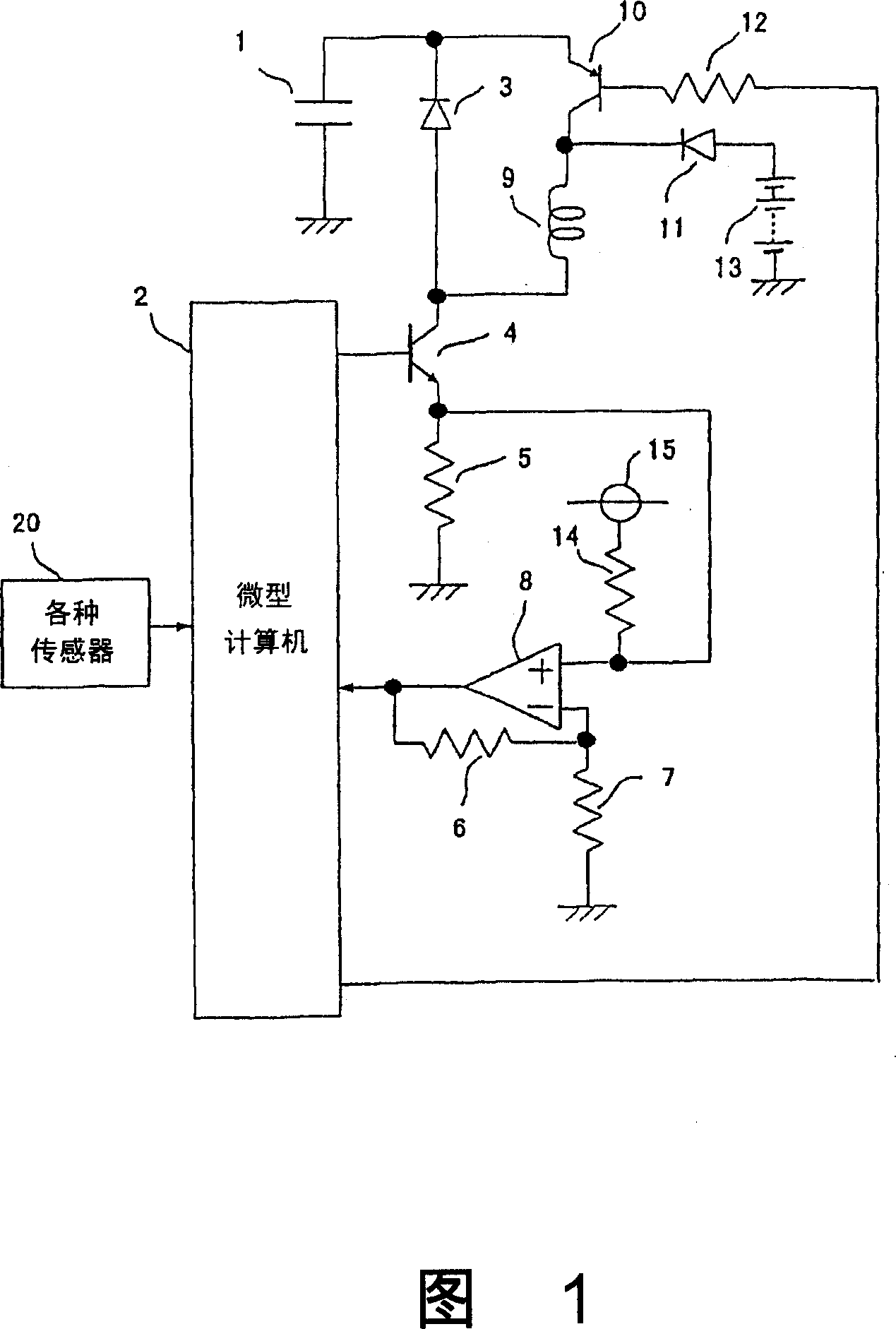
[0033] Fig. 1 shows a circuit diagram of a fuel injection system for an engine according to Embodiment 1 of the present invention.

[0034] The device shown in Figure 1 includes: a capacitor 1 with one end grounded, a microcomputer 2 with a CPU and various memory components, a diode 3 whose cathode is connected to the other end of the capacitor, and an output terminal (collector) connected to the anode of the diode 3 Transistor 4 , resistors 5 to 7 , 12 , 14 , operational amplifier 8 that detects the electromagnetic coil current flowing through transistor 4 , and electromagnetic coil 9 that is energized / disconnected by transistor 4 .

[0035] The device of Fig. 1 also includes: a transistor 10 inserted between one end of the electromagnetic coil 9 and the cathode of the diode 3, a diode 11 whose cathode is connected to one end of the electromagnetic coil 9, a battery 13 inserted between the anode of the diode 11 and the ground, connected by A bias power ...


PUM


Abstract

The invention provides a fuel injection device for engine which can detect the current on the electromagnetic winding in high precision so as to achieve the high precision of the control of the fuel injection module by arranged a biasing circuit on the detecting member for the electromagnetic winding current. The device comprises: a fuel injection module with functions that can drive a plunger to move forward and backward so as to suck the fuel or increase pressure to inject fuel when the electromagnetic winding 9 is electrified, and several sensors 20 for detecting the running state of the engine, and a control unit constituted by a micro-computer 2 for generating a driving signal to the fuel injection module according to the running state, and a current detecting member containing an operation amplifier 8 for detecting the electromagnetic winding current. The biasing current supplied by the biasing source 15 flow through the current detecting member firstly to stabilize the current value before electrified so as to achieve the high precision of the current detecting of the fuel injection module.

Description

technical field [0001] The present invention relates to a fuel injection device for an engine having a function of pressurizing fuel by reciprocating movement of a plunger and a function of a fuel injection valve, such as a new technology for engine fuel control of a two-wheeled vehicle. Background technique [0002] Conventionally, it is known to drive a solenoid type engine fuel injection device using energy stored in a capacitor (for example, refer to Patent Document 1). [0003] In the fuel injection system of this type of engine, the transistor that drives the electromagnetic coil is switched on and off under the control of a microcomputer, and the induced electromotive force generated by the electromagnetic coil charges the capacitor when the transistor is turned off. [0004] After the electromagnetic coil current is converted into a voltage, it is amplified by an operational amplifier and input to a microcomputer. In addition, it is also input to the microcomputer w...

Claims


Application Information

Patent Timeline
Patent Type & Authority Applications(China)
IPC IPC(8): F02D41/20F02D1/00
CPCY02T10/126
Inventor 濑良欣之
Owner MITSUBISHI ELECTRIC CORP
Why Eureka
Try Eureka